EP0307625A2 - Analyseur optique de gaz - Google Patents
Analyseur optique de gaz Download PDFInfo
- Publication number
- EP0307625A2 EP0307625A2 EP88113120A EP88113120A EP0307625A2 EP 0307625 A2 EP0307625 A2 EP 0307625A2 EP 88113120 A EP88113120 A EP 88113120A EP 88113120 A EP88113120 A EP 88113120A EP 0307625 A2 EP0307625 A2 EP 0307625A2
- Authority
- EP
- European Patent Office
- Prior art keywords
- gas
- radiation
- gas analyzer
- accordance
- gases
- Prior art date
- Legal status (The legal status is an assumption and is not a legal conclusion. Google has not performed a legal analysis and makes no representation as to the accuracy of the status listed.)
- Granted
Links
- 230000003287 optical effect Effects 0.000 title claims abstract description 14
- 239000007789 gas Substances 0.000 claims abstract description 94
- 230000005855 radiation Effects 0.000 claims abstract description 60
- 206010002091 Anaesthesia Diseases 0.000 claims abstract description 20
- 238000001949 anaesthesia Methods 0.000 claims abstract description 20
- 230000037005 anaesthesia Effects 0.000 claims abstract description 20
- 238000005259 measurement Methods 0.000 claims abstract description 17
- PIWKPBJCKXDKJR-UHFFFAOYSA-N Isoflurane Chemical compound FC(F)OC(Cl)C(F)(F)F PIWKPBJCKXDKJR-UHFFFAOYSA-N 0.000 claims abstract description 5
- JPGQOUSTVILISH-UHFFFAOYSA-N enflurane Chemical compound FC(F)OC(F)(F)C(F)Cl JPGQOUSTVILISH-UHFFFAOYSA-N 0.000 claims abstract description 5
- 229960000305 enflurane Drugs 0.000 claims abstract description 5
- BCQZXOMGPXTTIC-UHFFFAOYSA-N halothane Chemical compound FC(F)(F)C(Cl)Br BCQZXOMGPXTTIC-UHFFFAOYSA-N 0.000 claims abstract description 5
- 229960003132 halothane Drugs 0.000 claims abstract description 5
- 229960002725 isoflurane Drugs 0.000 claims abstract description 5
- VYPSYNLAJGMNEJ-UHFFFAOYSA-N Silicium dioxide Chemical compound O=[Si]=O VYPSYNLAJGMNEJ-UHFFFAOYSA-N 0.000 claims description 7
- 229910001369 Brass Inorganic materials 0.000 claims description 6
- 239000010951 brass Substances 0.000 claims description 6
- XLYOFNOQVPJJNP-UHFFFAOYSA-N water Substances O XLYOFNOQVPJJNP-UHFFFAOYSA-N 0.000 claims description 6
- 238000010521 absorption reaction Methods 0.000 claims description 5
- WUKWITHWXAAZEY-UHFFFAOYSA-L calcium difluoride Chemical compound [F-].[F-].[Ca+2] WUKWITHWXAAZEY-UHFFFAOYSA-L 0.000 claims description 4
- 229910001634 calcium fluoride Inorganic materials 0.000 claims description 4
- 238000012937 correction Methods 0.000 claims description 4
- 229910052751 metal Inorganic materials 0.000 claims description 4
- 239000002184 metal Substances 0.000 claims description 4
- 229910000831 Steel Inorganic materials 0.000 claims description 2
- 230000029058 respiratory gaseous exchange Effects 0.000 claims description 2
- 239000010959 steel Substances 0.000 claims description 2
- GQPLMRYTRLFLPF-UHFFFAOYSA-N Nitrous Oxide Chemical compound [O-][N+]#N GQPLMRYTRLFLPF-UHFFFAOYSA-N 0.000 abstract description 52
- CURLTUGMZLYLDI-UHFFFAOYSA-N Carbon dioxide Chemical compound O=C=O CURLTUGMZLYLDI-UHFFFAOYSA-N 0.000 abstract description 26
- 235000013842 nitrous oxide Nutrition 0.000 abstract description 26
- 229910002092 carbon dioxide Inorganic materials 0.000 abstract description 13
- 239000001569 carbon dioxide Substances 0.000 abstract description 8
- 238000012544 monitoring process Methods 0.000 abstract description 3
- 230000003444 anaesthetic effect Effects 0.000 abstract description 2
- 229960004424 carbon dioxide Drugs 0.000 abstract description 2
- 239000000126 substance Substances 0.000 description 9
- 230000000875 corresponding effect Effects 0.000 description 7
- 230000002745 absorbent Effects 0.000 description 4
- 239000002250 absorbent Substances 0.000 description 4
- 230000009102 absorption Effects 0.000 description 4
- 238000004458 analytical method Methods 0.000 description 4
- 239000000203 mixture Substances 0.000 description 4
- 239000010453 quartz Substances 0.000 description 4
- 230000008859 change Effects 0.000 description 3
- 238000013461 design Methods 0.000 description 3
- 238000001069 Raman spectroscopy Methods 0.000 description 2
- 229910001632 barium fluoride Inorganic materials 0.000 description 2
- 230000005540 biological transmission Effects 0.000 description 2
- 239000013078 crystal Substances 0.000 description 2
- 238000001514 detection method Methods 0.000 description 2
- 239000011888 foil Substances 0.000 description 2
- 239000011521 glass Substances 0.000 description 2
- 239000000463 material Substances 0.000 description 2
- 239000007787 solid Substances 0.000 description 2
- -1 20W halogen Chemical class 0.000 description 1
- MARUHZGHZWCEQU-UHFFFAOYSA-N 5-phenyl-2h-tetrazole Chemical compound C1=CC=CC=C1C1=NNN=N1 MARUHZGHZWCEQU-UHFFFAOYSA-N 0.000 description 1
- 229910004613 CdTe Inorganic materials 0.000 description 1
- 238000004566 IR spectroscopy Methods 0.000 description 1
- 239000005083 Zinc sulfide Substances 0.000 description 1
- 239000000654 additive Substances 0.000 description 1
- 230000000996 additive effect Effects 0.000 description 1
- 239000004411 aluminium Substances 0.000 description 1
- 229910052782 aluminium Inorganic materials 0.000 description 1
- XAGFODPZIPBFFR-UHFFFAOYSA-N aluminium Chemical compound [Al] XAGFODPZIPBFFR-UHFFFAOYSA-N 0.000 description 1
- 238000013459 approach Methods 0.000 description 1
- OYLGJCQECKOTOL-UHFFFAOYSA-L barium fluoride Chemical compound [F-].[F-].[Ba+2] OYLGJCQECKOTOL-UHFFFAOYSA-L 0.000 description 1
- 230000008901 benefit Effects 0.000 description 1
- 238000005266 casting Methods 0.000 description 1
- 239000000919 ceramic Substances 0.000 description 1
- 238000000748 compression moulding Methods 0.000 description 1
- 238000001816 cooling Methods 0.000 description 1
- 238000007516 diamond turning Methods 0.000 description 1
- 230000000694 effects Effects 0.000 description 1
- 238000002474 experimental method Methods 0.000 description 1
- 229910052732 germanium Inorganic materials 0.000 description 1
- GNPVGFCGXDBREM-UHFFFAOYSA-N germanium atom Chemical compound [Ge] GNPVGFCGXDBREM-UHFFFAOYSA-N 0.000 description 1
- 229910052736 halogen Inorganic materials 0.000 description 1
- 238000010438 heat treatment Methods 0.000 description 1
- 238000004949 mass spectrometry Methods 0.000 description 1
- 229910044991 metal oxide Inorganic materials 0.000 description 1
- 150000004706 metal oxides Chemical class 0.000 description 1
- 238000000034 method Methods 0.000 description 1
- 239000004033 plastic Substances 0.000 description 1
- 229920003023 plastic Polymers 0.000 description 1
- 238000003825 pressing Methods 0.000 description 1
- 230000008569 process Effects 0.000 description 1
- 229910001220 stainless steel Inorganic materials 0.000 description 1
- 239000010935 stainless steel Substances 0.000 description 1
- 238000012360 testing method Methods 0.000 description 1
- DRDVZXDWVBGGMH-UHFFFAOYSA-N zinc;sulfide Chemical compound [S-2].[Zn+2] DRDVZXDWVBGGMH-UHFFFAOYSA-N 0.000 description 1
Images

Classifications
-
- G—PHYSICS
- G01—MEASURING; TESTING
- G01N—INVESTIGATING OR ANALYSING MATERIALS BY DETERMINING THEIR CHEMICAL OR PHYSICAL PROPERTIES
- G01N21/00—Investigating or analysing materials by the use of optical means, i.e. using sub-millimetre waves, infrared, visible or ultraviolet light
- G01N21/17—Systems in which incident light is modified in accordance with the properties of the material investigated
- G01N21/25—Colour; Spectral properties, i.e. comparison of effect of material on the light at two or more different wavelengths or wavelength bands
- G01N21/31—Investigating relative effect of material at wavelengths characteristic of specific elements or molecules, e.g. atomic absorption spectrometry
- G01N21/35—Investigating relative effect of material at wavelengths characteristic of specific elements or molecules, e.g. atomic absorption spectrometry using infrared light
- G01N21/3504—Investigating relative effect of material at wavelengths characteristic of specific elements or molecules, e.g. atomic absorption spectrometry using infrared light for analysing gases, e.g. multi-gas analysis
-
- G—PHYSICS
- G01—MEASURING; TESTING
- G01N—INVESTIGATING OR ANALYSING MATERIALS BY DETERMINING THEIR CHEMICAL OR PHYSICAL PROPERTIES
- G01N21/00—Investigating or analysing materials by the use of optical means, i.e. using sub-millimetre waves, infrared, visible or ultraviolet light
- G01N21/17—Systems in which incident light is modified in accordance with the properties of the material investigated
- G01N21/25—Colour; Spectral properties, i.e. comparison of effect of material on the light at two or more different wavelengths or wavelength bands
- G01N21/31—Investigating relative effect of material at wavelengths characteristic of specific elements or molecules, e.g. atomic absorption spectrometry
- G01N2021/3129—Determining multicomponents by multiwavelength light
-
- G—PHYSICS
- G01—MEASURING; TESTING
- G01N—INVESTIGATING OR ANALYSING MATERIALS BY DETERMINING THEIR CHEMICAL OR PHYSICAL PROPERTIES
- G01N21/00—Investigating or analysing materials by the use of optical means, i.e. using sub-millimetre waves, infrared, visible or ultraviolet light
- G01N21/17—Systems in which incident light is modified in accordance with the properties of the material investigated
- G01N21/25—Colour; Spectral properties, i.e. comparison of effect of material on the light at two or more different wavelengths or wavelength bands
- G01N21/31—Investigating relative effect of material at wavelengths characteristic of specific elements or molecules, e.g. atomic absorption spectrometry
- G01N21/314—Investigating relative effect of material at wavelengths characteristic of specific elements or molecules, e.g. atomic absorption spectrometry with comparison of measurements at specific and non-specific wavelengths
- G01N2021/3166—Investigating relative effect of material at wavelengths characteristic of specific elements or molecules, e.g. atomic absorption spectrometry with comparison of measurements at specific and non-specific wavelengths using separate detectors and filters
-
- G—PHYSICS
- G01—MEASURING; TESTING
- G01N—INVESTIGATING OR ANALYSING MATERIALS BY DETERMINING THEIR CHEMICAL OR PHYSICAL PROPERTIES
- G01N2201/00—Features of devices classified in G01N21/00
- G01N2201/02—Mechanical
- G01N2201/023—Controlling conditions in casing
- G01N2201/0231—Thermostating
Definitions
- the present invention relates to an optical gas analyzer comprising a source of radiation and means for conducting the radiation obtained from this source through a gas sample and through a number of optical filters corresponding to the number of gases analyzed, each of which allows through a wavelength representative for the particular gas and especially absorbed by the gases analysed.
- Gas analyzers in accordance with the invention are intended primarily for the measurement of anaesthesia gases, e g halothane, isoflurane and enflurane, carbon dioxide and laughing gas and in particular in connection with anaesthization for monitoring the patient and administering the anaesthetic.
- anaesthesia gases e g halothane, isoflurane and enflurane
- carbon dioxide and laughing gas in particular in connection with anaesthization for monitoring the patient and administering the anaesthetic.
- IR-radiation is generated by a source of radiation which emits continuously radiation over a large wavelength range.
- an optical filter With the help of e g an optical filter the correct wavelength is chosen and the radiation is detected by an IR-detector which transduces the incident radiation energy to a proportional electrical signal.
- the choice of the analytical wavelength for a substance is very critical and wholly decisive for system characteristics such as accuray and quickness. In practice the choice is governed by whether several of the substances present absorb at or near the wavelength chosen, and whether it is technically/economically possible to measure radiation of this wavelenght to the specified accuracy requirement.
- the measuring system in some manner has to receive information indicating when the expiratory phase approaches the end.
- This information can be obtained through measurement of the carbon dioxide content, and instruments which measure the end-tidal carbon dioxide contents have been known for a long time (capnometers, capnographs).
- capnometers, capnographs On passage through the carbon dioxide meter, however, the sample gas will get mixed up and an anaesthesia gasmeter coupled in series will receive a phase-displaced and distorted sample, that is to say any curves recorded will receive a profile distortion.
- the invention thus relates to an optical gas analyzer comprising a source of radiation and means for conducting the radiation obtained from this source thorugh a gas sample and through a number of optical filters corresponding to the number of gases analysed, each of which allows through a wavelength representative for the particular gas and especially absorbed by the same to a number of detectors corresponding to the number of detectors corresponding to the number of gases analysed.
- the gas analyzer in accordance with the invention is characterized by means for the dividing up of the radiation path after passing of the gas sample for the purpose of simultaneous measurement of the gas concentration in respective detectors.
- the gas analyzer in accordance with the invention is intended in particular for the measurement of, among other things, anaesthesia gases in the inspired and/or expired air of a patient.
- the said optical filters are chosen so, therefore, that they allow through wavelengths only between 3,8-5 ⁇ and 8-14 ⁇ , that is to say neither higher, nor lower, nor any wavelengths in between.
- a filter is selected which is permeable for wavelengths 8,81 ⁇ , in combination with an N2O filter and a CO2 filter which are premeable for wavelenghts especially absorbed by these gases, preferably 3,90 ⁇ and 4,26 ⁇ respectively.
- the N2O content here may affect the measuring result for the anaestesia gases and for this reason suitable means are provided for correction of the absorption caused by N2O recorded by the anaesthesia detector as a function of the measured value obtained at the same time in the N2O detector.
- the said means for the division of the radiation path consists apropriately of a mirror arrangement which preferably divides the radiation path into a number of equivalent ray bundles corresponding to the number of gases analysed. It will be obvious, however, to those versed in the art that other arrangements too may be used, e g collective optical lenses, provided these allow through the wavelengths selected.
- the gas analysed is passed through a cell or the like with two windows of, for example, CaF2 (calcium fluoride) transparent for the radiation, placed in the radiation path.
- CaF2 calcium fluoride
- suitable material might be mentioned BaF2 (barium fluoride), CdTe (cadmium telluride), Ge (germanium) and ZnS (zinc sulphide -Itran II).
- the same is provided with means for the continuous conducting of the gas mixture analysed through the radiation path and with means, e g a rotating diaphragm, for the regular interruption of the radiation path so as to obtain intermittent meauring values.
- the gas analyzer in accordance with the invention is provided appropriately with means for utilizing the measuring values obtained in the CO2 detector for the determination of the end of the repective expiratory phase.
- microcomputers included in the analyzer can be programmed so that they indicate the end of each expiratory phase.
- the source of radiation appropriately consists of an IR-source which emits a continous radiation over a large wavelength range, e g a thermal lamp with an envelope of quartz glass which absorbs the thermal radiation from the incandescent filament and in this way is heated so that it in turn gives off the desired radiation.
- This radiation can be amplified within the desired wavelength range, if the heat source outermost is surrounded by a thin metal envelope with oxidized outer surface, e g an envelope of steel or brass, preferably black-nickel-plated brass.
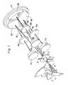
- Figure 1 thus shows a schematic illustration of the radiaion path in a gas analyzer according to the invention.
- a cylindrical light source 1 which, for example, may consist of a heated body.
- the radiation from the source passes a rotating diaphragm 2 which chops it up in time (on account of the detection principle).
- the radiation passes a conically shaped cell 3 which is delimited by two windows 4 and 5 which are transparent for the actual radiation.
- the window 4 is shown separate from the rest of the cell.
- Numeral 6 refers to the inlet for the gas mixture examined and 7 to the outlet for the same.
- the radiation is conducted further to a three-part mirror 8 which divides up the original ray bundle 9 into three part bundles 9a, 9b and 9c respectively to be directed through three filters 10a, 10b and 10c respectively and further from these to three detectors 11a, 11b and 11c respectively.
- the detector 11a is constituted preferably of a CO2 detector, the filter 10a being of the kind which allows through the wavelength 4,26 ⁇ representative for CO2.
- the detector 11b at the same time may be constitued of an N2O detector, the filter 10b being selected to allow through a wavelength representative for the same, e g 3,90 ⁇ .
- the detector 11c finally is used for the actual measurement of the anaesthesia gas used.
- the filter 10c in such a case is chosen so that it allows through a wavelength representative for this, e g 8,81 ⁇ .
- Each part of mirror 8a, 8b and 8c respectively is designed as a segment of a circle of 120°.
- the parts of mirror moreover, have an "off-axis" placing in relation to the cuvette, whose windows therefore will be pictured three times on a periphery of a circle. In this manner the radiation can be conducted easily via the respective filter to the respective detector for simultaneously reading of the respective amounts of gas.
- the wavelength 3,90 ⁇ preferably is used here.
- the wavelength 3 anae preferably is used here.
- the appropriate wavelength is 8,81 ⁇ .
- This wavelength moreover, has the advantage that it can be used for the analysis of all the abovementioned three anaesthesia gases, which renders the design much less expensive. The analysis is slightly disturbed, though, by laughing gas, so that the same has to be measured separately for compensation. How this compensation is done will be described in more detail in the following.
- the laughing gas content is also of direct clinical interest.
- the radiation which passes the cell comprising the gas sample, thus has to be divided over three filter/detector systems.
- spatial division is used, and the three parts of mirror each forward their part of the total radiation to the respective detector.
- the parts of mirror also fulfil the task of collecting the radiation from the IR source over a large solid angle. Since pyroelectric detectors create quite a lot of noise, they call for plenty of signal. This is particularly important in the rapid detection which is needed for end-tidal measurements.
- the amount of radiation which strikes the detector is directly proportional to the solid angle under which the detector "sees” the light source, or the angle under which the mirror collects the radiation.
- the three parts of the mirror are functionally separate units but may be manufactured as one component e g by casting or compression moulding in plastics, diamond turning in aluminium or pressing of glass.
- a hot-body radiator As a source of radiation preferably a hot-body radiator is used which may consist of an ordinary 12V/20W halogen bulb run at approx. 12W.
- the envelope of the bulb may consist of quartz glass which absorbs all IR radiation from the incandescent wire and is heated. The envelope in turn gives off radiation of longer wavelengths according to Planck's radiation law. It is thus the hot glass envelope which constitutes the actual source.
- This source is used today in this form in a CO2 analyzer sold by the applicant under the name of ELIZA.
- quartz has a relatively low coefficient of emission at the particular wavelengths and the source, therefore, is wholly ineffective at, for example, a wavelength of 8,8 ⁇ .
- Certain metal oxides are known to have high coefficients of emission in infrared.
- the efficiency of the source can be raised, therefore, if the quartz envelope is surrounded by a thin metal envelope whose surface has been oxidized.
- This envelope may be constituted of a tube with a wall thickness of 0,5 mm which has been oxidized either in a flame or chemically.
- Successful experiments have been carried out with brass and stainless steel which both increased the radiation efficiency 2,5-2,7 times at 8,8 ⁇ and approx. 1,5 times at 4,25 ⁇ . Corresponding improvements and even better results ought to be obtainable with black-nickel-plated brass.
- fig 3 is shown a schematic sketch illustrating how laughing gas (N2O) disturbs the analysis of anaesthesia gas (AA) if this consists of, for example, halothane, isoflurane and enflurane.
- AA anaesthesia gas
- the correction is based on the following:
- fig 2 is shown in a little more detail, but still schematically, a practical embodiment of the subject of the invention.
- the light source used thus has been designated 1 and a rotating diaphragm 2.
- the cell is designated 3 and its two windows 4 and 5 respectively.
- the gas mixture analysed is introduced via the inlet 6 and discharged via the outlet marked as a point 7.
- the mirror used has been designated 8 and it comprises parts 8a,8b and 8c.
- the radiation path has been marked only for the mirror part 8c which directs its part of the radiation to the detector 11c via the filter 10c.
- the cell, the mirror, the filter and the detectors are arranged in a rigid envelope 12 comprising, among other things, a distance tube 13 to make possible, among other things, the keeping constant of the temperature and a firm exact position of the particular item.
- a distance tube 13 Around the distance tube 13 has been wound a thin heating foil 14a. This heats on the one hand the distance tube 13 and the items enclosed therein, on the other hand a pipeline 14 wound outside the foil for the gas examined, which is thus also heated to a suitable temperature.
- Numeral 15 designates the motor for the rotating diaphragm 2 and 16 a cooling flange.
- Numeral 17 designates a protection for the diaphragm 2 and 18 a circuit board indicated symbolically which is connected to an amplifier 19.
- the circuit board 18 comprises, or is connected to, a microcomputer not shown for the control of the desired measuring process.
- Numeral 20 finally designates a holder for the heat source 1, e g a standard ceramic holder.
Applications Claiming Priority (2)
| Application Number | Priority Date | Filing Date | Title |
|---|---|---|---|
| SE8703564 | 1987-09-15 | ||
| SE8703564A SE459126B (sv) | 1987-09-15 | 1987-09-15 | Optisk gasanalysator |
Publications (3)
| Publication Number | Publication Date |
|---|---|
| EP0307625A2 true EP0307625A2 (fr) | 1989-03-22 |
| EP0307625A3 EP0307625A3 (en) | 1990-05-16 |
| EP0307625B1 EP0307625B1 (fr) | 1994-04-20 |
Family
ID=20369573
Family Applications (1)
| Application Number | Title | Priority Date | Filing Date |
|---|---|---|---|
| EP88113120A Expired - Lifetime EP0307625B1 (fr) | 1987-09-15 | 1988-08-12 | Analyseur optique de gaz |
Country Status (6)
| Country | Link |
|---|---|
| US (1) | US5130544A (fr) |
| EP (1) | EP0307625B1 (fr) |
| JP (1) | JP2788036B2 (fr) |
| DE (1) | DE3889181T2 (fr) |
| ES (1) | ES2050683T3 (fr) |
| SE (1) | SE459126B (fr) |
Cited By (7)
| Publication number | Priority date | Publication date | Assignee | Title |
|---|---|---|---|---|
| EP0550396A2 (fr) * | 1992-01-03 | 1993-07-07 | Artema Medical Ab | Dispositif d'analyse de gaz |
| DE4214840A1 (de) * | 1992-05-05 | 1993-11-11 | Draegerwerk Ag | Vorrichtung zur gleichzeitigen Analyse verschiedener Bestandteile eines Fluids |
| EP0732580A2 (fr) * | 1995-03-13 | 1996-09-18 | Ohmeda Inc. | Dispositif pour l'identification automatique des prélèvements de gaz |
| EP0795744A1 (fr) * | 1996-03-14 | 1997-09-17 | Instrumentarium Oy | Analyse de mélanges gazeux par méthode infrarouge |
| US5739535A (en) * | 1995-10-25 | 1998-04-14 | Dragerwerk Aktiengesellschaft | Optical gas analyzer |
| FR2828932A1 (fr) * | 2001-08-21 | 2003-02-28 | Draeger Medical Ag | Procede d'identification et de determination de la pression partielle de deux gaz dans un melange de gaz anesthesiants inconnus |
| CN104819958A (zh) * | 2015-05-19 | 2015-08-05 | 清华大学 | 傅里叶变换红外光谱气体检测中自动消除水汽干扰的方法与装置 |
Families Citing this family (34)
| Publication number | Priority date | Publication date | Assignee | Title |
|---|---|---|---|---|
| US5095913A (en) * | 1989-09-01 | 1992-03-17 | Critikon, Inc. | Shutterless optically stabilized capnograph |
| JP2792782B2 (ja) * | 1992-03-11 | 1998-09-03 | 東京電力株式会社 | ガス濃度測定方法およびその測定装置 |
| JP2744728B2 (ja) * | 1992-03-11 | 1998-04-28 | 東京電力株式会社 | ガス濃度測定方法およびその測定装置 |
| US5515859A (en) * | 1993-08-24 | 1996-05-14 | Colorado Health Care Research Corp. | Myocardial infarction and ischemia detection method and apparatus |
| US5570697A (en) * | 1994-07-15 | 1996-11-05 | Vixel Corporation | Sensor for analyzing molecular species |
| US5545897A (en) * | 1994-10-04 | 1996-08-13 | Santa Barbara Research Center | Optically-based chemical detection system |
| US5497003A (en) * | 1995-02-15 | 1996-03-05 | Servo Corporation Of America | Pyroelectric detector array with optical filter elements |
| DE19628310C2 (de) * | 1995-10-25 | 1998-05-14 | Draegerwerk Ag | Optischer Gasanalysator |
| US5870185A (en) * | 1996-10-21 | 1999-02-09 | C.F.C. Technology, Inc. | Apparatus and method for fluid analysis |
| US5886348A (en) * | 1997-02-14 | 1999-03-23 | American Intell-Sensors Corporation | Non-dispersive infrared gas analyzer with interfering gas correction |
| US5942755A (en) * | 1997-02-19 | 1999-08-24 | Dragerwerk Ag | Infrared optical gas-measuring system |
| US5931161A (en) * | 1998-03-18 | 1999-08-03 | Datex-Ohmeda, Inc. | On-airway respiratory gas monitor employing transformed infrared signals |
| IL130371A (en) | 1999-06-08 | 2004-06-01 | Oridion Medical Ltd | Capnography waveform interpreter |
| US6277081B1 (en) * | 1999-05-18 | 2001-08-21 | Invivo Research, Inc. | Anesthetic gas detection apparatus |
| GB2389177B (en) * | 2002-05-31 | 2006-03-15 | Marconi Applied Techn Ltd | Gas sensors |
| GB2395259A (en) * | 2002-11-07 | 2004-05-19 | E2V Tech Uk Ltd | Gas sensor with predetermined optical paths between its different detectors |
| US7301148B2 (en) * | 2003-04-23 | 2007-11-27 | Battelle Memorial Institute | Methods and systems for remote detection of gases |
| DE102004030855A1 (de) * | 2004-06-25 | 2006-01-12 | Tyco Electronics Raychem Gmbh | Verfahren zur Reduzierung von Kondenswasser bei Gassensoranordnungen |
| JP4417223B2 (ja) * | 2004-10-21 | 2010-02-17 | 高圧ガス保安協会 | 濃度測定装置 |
| CN1877304B (zh) * | 2005-06-10 | 2010-04-28 | 深圳迈瑞生物医疗电子股份有限公司 | 单种麻醉气体类型编码识别的方法和装置 |
| US8062221B2 (en) | 2005-09-30 | 2011-11-22 | Nellcor Puritan Bennett Llc | Sensor for tissue gas detection and technique for using the same |
| US20070106134A1 (en) | 2005-11-10 | 2007-05-10 | O'neil Michael P | Medical sensor and technique for using the same |
| US8431087B2 (en) | 2006-09-25 | 2013-04-30 | Covidien Lp | Carbon dioxide detector having borosilicate substrate |
| US8449834B2 (en) | 2006-09-25 | 2013-05-28 | Covidien Lp | Carbon dioxide detector having borosilicate substrate |
| US8431088B2 (en) | 2006-09-25 | 2013-04-30 | Covidien Lp | Carbon dioxide detector having borosilicate substrate |
| US7992561B2 (en) | 2006-09-25 | 2011-08-09 | Nellcor Puritan Bennett Llc | Carbon dioxide-sensing airway products and technique for using the same |
| US8420405B2 (en) | 2006-09-25 | 2013-04-16 | Covidien Lp | Carbon dioxide detector having borosilicate substrate |
| US8396524B2 (en) | 2006-09-27 | 2013-03-12 | Covidien Lp | Medical sensor and technique for using the same |
| DE102008005572B4 (de) * | 2008-01-22 | 2011-04-14 | Smartgas Mikrosensorik Gmbh | Messverfahren und Gassensor zur simultanen Erfassung der Konzentration zweier unterschiedlicher Gase |
| DE102009022465A1 (de) * | 2009-05-23 | 2010-11-25 | Bernd Baumann | Verfahren zur optischen Druckmessung |
| US20140124673A1 (en) * | 2010-12-20 | 2014-05-08 | Binder Gmbh | Measuring system for measuring the co2 concentration in a climate cabinet or an incubator |
| US8785857B2 (en) * | 2011-09-23 | 2014-07-22 | Msa Technology, Llc | Infrared sensor with multiple sources for gas measurement |
| CN110057762B (zh) * | 2019-03-13 | 2021-11-02 | 电子科技大学 | 一种激光光谱痕量气体检测技术中的气体深度干燥方法 |
| RU204428U1 (ru) * | 2021-02-25 | 2021-05-24 | Федеральное государственное бюджетное образовательное учреждение высшего образования "Тверской государственный технический университет" | Инфракрасный термохимический детектор газов |
Citations (9)
| Publication number | Priority date | Publication date | Assignee | Title |
|---|---|---|---|---|
| US2806144A (en) * | 1953-09-15 | 1957-09-10 | Phillips Petroleum Co | Infrared analyzer |
| US3702397A (en) * | 1970-02-17 | 1972-11-07 | Nat Res Dev | Infra-red gas detectors |
| US3836255A (en) * | 1972-04-06 | 1974-09-17 | M Schuman | Spectrometric substance analyzer employing temperature modulation |
| DE2727976B2 (de) * | 1977-06-22 | 1979-09-06 | Kernforschungszentrum Karlsruhe Gmbh, 7500 Karlsruhe | Vorrichtung zur Messung der Konzentration mindestens einer Komponente eines Gasgemisches und Verfahren zum Eichen derselben |
| US4180734A (en) * | 1977-02-18 | 1979-12-25 | Siemens Aktiengesellschaft | Gas analyzer |
| US4320297A (en) * | 1979-11-29 | 1982-03-16 | Beckman Instruments, Inc. | Split detector |
| WO1983000613A1 (fr) * | 1981-08-24 | 1983-03-03 | Andros Analyzers Inc | Analyseur du gaz carbonique contenu dans l'air expire |
| GB2117112A (en) * | 1982-03-11 | 1983-10-05 | Draegerwerk Ag | Optical multi-ray gas-detecting apparatus |
| EP0123458A2 (fr) * | 1983-04-05 | 1984-10-31 | Edinburgh Sensors Limited | Détecteur de gaz par absorption de l'infrarouge |
Family Cites Families (11)
| Publication number | Priority date | Publication date | Assignee | Title |
|---|---|---|---|---|
| US3941487A (en) * | 1973-04-16 | 1976-03-02 | Beckman Instruments, Inc. | Colorimetric fluid analyzer |
| US3860344A (en) * | 1973-05-10 | 1975-01-14 | Honeywell Inc | Multi-component infrared analyzer |
| JPS5231783A (en) * | 1975-09-05 | 1977-03-10 | Japan Spectroscopic Co | Multiple wavelength colorimeter |
| DE2906742A1 (de) * | 1978-02-23 | 1979-09-20 | Martin Leslie Tatnall | Einrichtung zur ueberwachung der konzentration eines anaestheticums in der ausatmungsluft eines patienten |
| DE2808033A1 (de) * | 1978-02-24 | 1979-08-30 | Siemens Ag | Einrichtung zur unterdrueckung der wasserdampf-querempfindlichkeit bei einem nicht dispersiven infrarot-gasanalysator |
| US4356394A (en) * | 1981-01-30 | 1982-10-26 | Baxter Travenol Laboratories, Inc. | Apparatus for applying radiant beam |
| DE3302656C2 (de) * | 1983-01-27 | 1985-04-18 | Gkss - Forschungszentrum Geesthacht Gmbh, 2054 Geesthacht | Verfahren und Vorrichtung zur Bestimmung von in natürliche Wässer in Lösung gegangenen Kohlenwasserstoffen |
| US4618771A (en) * | 1983-11-14 | 1986-10-21 | Beckman Industrial Corporation | Non-dispersive infrared analyzer having improved infrared source and detecting assemblies |
| US4749276A (en) * | 1986-01-23 | 1988-06-07 | Mcdonnell Douglas Corporation | Long path absorption cell |
| JPS62127659U (fr) * | 1986-02-04 | 1987-08-13 | ||
| US4914720A (en) * | 1986-12-04 | 1990-04-03 | Cascadia Technology Corporation | Gas analyzers |
-
1987
- 1987-09-15 SE SE8703564A patent/SE459126B/sv not_active IP Right Cessation
-
1988
- 1988-08-12 ES ES88113120T patent/ES2050683T3/es not_active Expired - Lifetime
- 1988-08-12 DE DE3889181T patent/DE3889181T2/de not_active Expired - Fee Related
- 1988-08-12 EP EP88113120A patent/EP0307625B1/fr not_active Expired - Lifetime
- 1988-09-09 US US07/242,698 patent/US5130544A/en not_active Expired - Fee Related
- 1988-09-14 JP JP63228926A patent/JP2788036B2/ja not_active Expired - Lifetime
Patent Citations (9)
| Publication number | Priority date | Publication date | Assignee | Title |
|---|---|---|---|---|
| US2806144A (en) * | 1953-09-15 | 1957-09-10 | Phillips Petroleum Co | Infrared analyzer |
| US3702397A (en) * | 1970-02-17 | 1972-11-07 | Nat Res Dev | Infra-red gas detectors |
| US3836255A (en) * | 1972-04-06 | 1974-09-17 | M Schuman | Spectrometric substance analyzer employing temperature modulation |
| US4180734A (en) * | 1977-02-18 | 1979-12-25 | Siemens Aktiengesellschaft | Gas analyzer |
| DE2727976B2 (de) * | 1977-06-22 | 1979-09-06 | Kernforschungszentrum Karlsruhe Gmbh, 7500 Karlsruhe | Vorrichtung zur Messung der Konzentration mindestens einer Komponente eines Gasgemisches und Verfahren zum Eichen derselben |
| US4320297A (en) * | 1979-11-29 | 1982-03-16 | Beckman Instruments, Inc. | Split detector |
| WO1983000613A1 (fr) * | 1981-08-24 | 1983-03-03 | Andros Analyzers Inc | Analyseur du gaz carbonique contenu dans l'air expire |
| GB2117112A (en) * | 1982-03-11 | 1983-10-05 | Draegerwerk Ag | Optical multi-ray gas-detecting apparatus |
| EP0123458A2 (fr) * | 1983-04-05 | 1984-10-31 | Edinburgh Sensors Limited | Détecteur de gaz par absorption de l'infrarouge |
Cited By (13)
| Publication number | Priority date | Publication date | Assignee | Title |
|---|---|---|---|---|
| US5326973A (en) * | 1992-01-03 | 1994-07-05 | Artema Medical Ab | Device for gas analysis |
| EP0550396A3 (en) * | 1992-01-03 | 1994-08-17 | Artema Medical Ab | Device for gas analysis |
| EP0550396A2 (fr) * | 1992-01-03 | 1993-07-07 | Artema Medical Ab | Dispositif d'analyse de gaz |
| DE4214840A1 (de) * | 1992-05-05 | 1993-11-11 | Draegerwerk Ag | Vorrichtung zur gleichzeitigen Analyse verschiedener Bestandteile eines Fluids |
| EP0732580A2 (fr) * | 1995-03-13 | 1996-09-18 | Ohmeda Inc. | Dispositif pour l'identification automatique des prélèvements de gaz |
| EP0732580A3 (fr) * | 1995-03-13 | 1997-01-29 | Ohmeda Inc | Dispositif pour l'identification automatique des prélèvements de gaz |
| US5739535A (en) * | 1995-10-25 | 1998-04-14 | Dragerwerk Aktiengesellschaft | Optical gas analyzer |
| EP0795744A1 (fr) * | 1996-03-14 | 1997-09-17 | Instrumentarium Oy | Analyse de mélanges gazeux par méthode infrarouge |
| US5908789A (en) * | 1996-03-14 | 1999-06-01 | Instrumentarium Oy | Analysis of gas mixtures with an infrared method |
| FR2828932A1 (fr) * | 2001-08-21 | 2003-02-28 | Draeger Medical Ag | Procede d'identification et de determination de la pression partielle de deux gaz dans un melange de gaz anesthesiants inconnus |
| DE10140998C2 (de) * | 2001-08-21 | 2003-07-17 | Draeger Medical Ag | Verfahren zur Identifikation und Partialdruckbestimmung von zwei Gasen in einem unbekannten Anästhesiegasgemisch |
| CN104819958A (zh) * | 2015-05-19 | 2015-08-05 | 清华大学 | 傅里叶变换红外光谱气体检测中自动消除水汽干扰的方法与装置 |
| CN104819958B (zh) * | 2015-05-19 | 2017-03-29 | 清华大学 | 傅里叶变换红外光谱气体检测中自动消除水汽干扰的方法与装置 |
Also Published As
| Publication number | Publication date |
|---|---|
| DE3889181T2 (de) | 1994-08-04 |
| US5130544A (en) | 1992-07-14 |
| SE8703564L (sv) | 1989-03-16 |
| ES2050683T3 (es) | 1994-06-01 |
| DE3889181D1 (de) | 1994-05-26 |
| JPH01100437A (ja) | 1989-04-18 |
| EP0307625A3 (en) | 1990-05-16 |
| JP2788036B2 (ja) | 1998-08-20 |
| SE459126B (sv) | 1989-06-05 |
| SE8703564D0 (sv) | 1987-09-15 |
| EP0307625B1 (fr) | 1994-04-20 |
Similar Documents
| Publication | Publication Date | Title |
|---|---|---|
| EP0307625B1 (fr) | Analyseur optique de gaz | |
| US5222389A (en) | Multi-channel gas sample chamber | |
| US5341214A (en) | NDIR gas analysis using spectral ratioing technique | |
| EP0568549B1 (fr) | Chambre d'echantillonnage de gaz amelioree | |
| JP4729215B2 (ja) | 同位体比率を測定するための赤外分光計 | |
| US4011859A (en) | Method for continuously measuring the CO2 content in breathing gases | |
| US4370553A (en) | Contaminated sample gas analyzer and gas cell therefor | |
| US5932877A (en) | High performance side stream infrared gas analyzer | |
| FI102570B (fi) | Menetelmä ja laite alkoholipitoisuuden määrittämiseksi kaasuseoksesta | |
| US5942755A (en) | Infrared optical gas-measuring system | |
| EP1332346B1 (fr) | Analyseur de gaz respiratoires | |
| US6571622B2 (en) | Combined respiratory flow sensor | |
| JPH09510550A (ja) | 呼吸ガス分析器 | |
| CA2256729A1 (fr) | Dispositif pour spectroscopie d'absorption non dispersive dans l'infrarouge et procede de mesure de rapports isotopiques dans des echantillons gazeux | |
| US4050823A (en) | Apparatus for continuously measuring the CO2 content in breathing gases | |
| JPH102857A (ja) | 赤外法によるガス混合物の分析 | |
| US6191421B1 (en) | Gas analyzer using infrared radiation to determine the concentration of a target gas in a gaseous mixture | |
| JPS6312938A (ja) | ガス分析装置及びガス分析方法 | |
| US5731583A (en) | Folded optical path gas analyzer with cylindrical chopper | |
| AU637827B2 (en) | Shutterless optically stabilized capnograph | |
| WO1996001418A1 (fr) | Analyse de gaz a ir non dispersif a technique de proportionalisation spectrale | |
| JP2001324446A (ja) | 同位体ガス測定装置 | |
| JP3126759B2 (ja) | 光学式分析装置 | |
| US3651322A (en) | Device for gas analysis | |
| JPS6329240Y2 (fr) |
Legal Events
| Date | Code | Title | Description |
|---|---|---|---|
| PUAI | Public reference made under article 153(3) epc to a published international application that has entered the european phase |
Free format text: ORIGINAL CODE: 0009012 |
|
| AK | Designated contracting states |
Kind code of ref document: A2 Designated state(s): BE CH DE ES FR GB IT LI NL |
|
| PUAL | Search report despatched |
Free format text: ORIGINAL CODE: 0009013 |
|
| AK | Designated contracting states |
Kind code of ref document: A3 Designated state(s): BE CH DE ES FR GB IT LI NL |
|
| 17P | Request for examination filed |
Effective date: 19901018 |
|
| 17Q | First examination report despatched |
Effective date: 19920323 |
|
| GRAA | (expected) grant |
Free format text: ORIGINAL CODE: 0009210 |
|
| ITF | It: translation for a ep patent filed |
Owner name: BARZANO' E ZANARDO MILANO S.P.A. |
|
| AK | Designated contracting states |
Kind code of ref document: B1 Designated state(s): BE CH DE ES FR GB IT LI NL |
|
| REF | Corresponds to: |
Ref document number: 3889181 Country of ref document: DE Date of ref document: 19940526 |
|
| ET | Fr: translation filed | ||
| PLBI | Opposition filed |
Free format text: ORIGINAL CODE: 0009260 |
|
| 26 | Opposition filed |
Opponent name: DRAEGERWERK AKTIENGESELLSCHAFT Effective date: 19950113 |
|
| NLR1 | Nl: opposition has been filed with the epo |
Opponent name: DRAEGERWERK AKTIENGESELLSCHAFT |
|
| REG | Reference to a national code |
Ref country code: CH Ref legal event code: PFA Free format text: ENGSTROEM MEDICAL AB |
|
| NLT1 | Nl: modifications of names registered in virtue of documents presented to the patent office pursuant to art. 16 a, paragraph 1 |
Owner name: ENGSTROEM MEDICAL AKTIEBOLAG |
|
| REG | Reference to a national code |
Ref country code: FR Ref legal event code: CD |
|
| REG | Reference to a national code |
Ref country code: ES Ref legal event code: PC2A Owner name: ENGSTROM MEDICAL AB |
|
| RAP2 | Party data changed (patent owner data changed or rights of a patent transferred) |
Owner name: ENGSTROEM MEDICAL AB |
|
| NLT2 | Nl: modifications (of names), taken from the european patent patent bulletin |
Owner name: ENGSTROEM MEDICAL AB |
|
| PLBO | Opposition rejected |
Free format text: ORIGINAL CODE: EPIDOS REJO |
|
| PLBN | Opposition rejected |
Free format text: ORIGINAL CODE: 0009273 |
|
| STAA | Information on the status of an ep patent application or granted ep patent |
Free format text: STATUS: OPPOSITION REJECTED |
|
| 27O | Opposition rejected |
Effective date: 19970605 |
|
| NLR2 | Nl: decision of opposition | ||
| PGFP | Annual fee paid to national office [announced via postgrant information from national office to epo] |
Ref country code: CH Payment date: 20000721 Year of fee payment: 13 |
|
| PGFP | Annual fee paid to national office [announced via postgrant information from national office to epo] |
Ref country code: NL Payment date: 20000724 Year of fee payment: 13 |
|
| PGFP | Annual fee paid to national office [announced via postgrant information from national office to epo] |
Ref country code: BE Payment date: 20000809 Year of fee payment: 13 |
|
| PGFP | Annual fee paid to national office [announced via postgrant information from national office to epo] |
Ref country code: ES Payment date: 20000908 Year of fee payment: 13 |
|
| PGFP | Annual fee paid to national office [announced via postgrant information from national office to epo] |
Ref country code: FR Payment date: 20010718 Year of fee payment: 14 |
|
| PGFP | Annual fee paid to national office [announced via postgrant information from national office to epo] |
Ref country code: GB Payment date: 20010720 Year of fee payment: 14 |
|
| PG25 | Lapsed in a contracting state [announced via postgrant information from national office to epo] |
Ref country code: ES Free format text: LAPSE BECAUSE OF NON-PAYMENT OF DUE FEES Effective date: 20010813 |
|
| PG25 | Lapsed in a contracting state [announced via postgrant information from national office to epo] |
Ref country code: LI Free format text: LAPSE BECAUSE OF NON-PAYMENT OF DUE FEES Effective date: 20010831 Ref country code: CH Free format text: LAPSE BECAUSE OF NON-PAYMENT OF DUE FEES Effective date: 20010831 Ref country code: BE Free format text: LAPSE BECAUSE OF NON-PAYMENT OF DUE FEES Effective date: 20010831 |
|
| REG | Reference to a national code |
Ref country code: GB Ref legal event code: IF02 |
|
| BERE | Be: lapsed |
Owner name: ENGSTROM MEDICAL A.B. Effective date: 20010831 |
|
| PG25 | Lapsed in a contracting state [announced via postgrant information from national office to epo] |
Ref country code: NL Free format text: LAPSE BECAUSE OF NON-PAYMENT OF DUE FEES Effective date: 20020301 |
|
| REG | Reference to a national code |
Ref country code: CH Ref legal event code: PL |
|
| NLV4 | Nl: lapsed or anulled due to non-payment of the annual fee |
Effective date: 20020301 |
|
| PG25 | Lapsed in a contracting state [announced via postgrant information from national office to epo] |
Ref country code: GB Free format text: LAPSE BECAUSE OF NON-PAYMENT OF DUE FEES Effective date: 20020812 |
|
| PGFP | Annual fee paid to national office [announced via postgrant information from national office to epo] |
Ref country code: DE Payment date: 20020830 Year of fee payment: 15 |
|
| GBPC | Gb: european patent ceased through non-payment of renewal fee |
Effective date: 20020812 |
|
| PG25 | Lapsed in a contracting state [announced via postgrant information from national office to epo] |
Ref country code: FR Free format text: LAPSE BECAUSE OF NON-PAYMENT OF DUE FEES Effective date: 20030430 |
|
| REG | Reference to a national code |
Ref country code: FR Ref legal event code: ST |
|
| PG25 | Lapsed in a contracting state [announced via postgrant information from national office to epo] |
Ref country code: DE Free format text: LAPSE BECAUSE OF NON-PAYMENT OF DUE FEES Effective date: 20040302 |
|
| REG | Reference to a national code |
Ref country code: ES Ref legal event code: FD2A Effective date: 20020911 |
|
| PG25 | Lapsed in a contracting state [announced via postgrant information from national office to epo] |
Ref country code: IT Free format text: LAPSE BECAUSE OF NON-PAYMENT OF DUE FEES;WARNING: LAPSES OF ITALIAN PATENTS WITH EFFECTIVE DATE BEFORE 2007 MAY HAVE OCCURRED AT ANY TIME BEFORE 2007. THE CORRECT EFFECTIVE DATE MAY BE DIFFERENT FROM THE ONE RECORDED. Effective date: 20050812 |