EP1552912B1 - Aufschneidemaschine zum Aufschneiden von Lebensmittelriegeln - Google Patents
Aufschneidemaschine zum Aufschneiden von Lebensmittelriegeln Download PDFInfo
- Publication number
- EP1552912B1 EP1552912B1 EP05007281A EP05007281A EP1552912B1 EP 1552912 B1 EP1552912 B1 EP 1552912B1 EP 05007281 A EP05007281 A EP 05007281A EP 05007281 A EP05007281 A EP 05007281A EP 1552912 B1 EP1552912 B1 EP 1552912B1
- Authority
- EP
- European Patent Office
- Prior art keywords
- food
- blade
- cutting blade
- cutting
- slicing machine
- Prior art date
- Legal status (The legal status is an assumption and is not a legal conclusion. Google has not performed a legal analysis and makes no representation as to the accuracy of the status listed.)
- Expired - Lifetime
Links
Images


Classifications
-
- B—PERFORMING OPERATIONS; TRANSPORTING
- B26—HAND CUTTING TOOLS; CUTTING; SEVERING
- B26D—CUTTING; DETAILS COMMON TO MACHINES FOR PERFORATING, PUNCHING, CUTTING-OUT, STAMPING-OUT OR SEVERING
- B26D7/00—Details of apparatus for cutting, cutting-out, stamping-out, punching, perforating, or severing by means other than cutting
- B26D7/27—Means for performing other operations combined with cutting
- B26D7/32—Means for performing other operations combined with cutting for conveying or stacking cut product
- B26D7/325—Means for performing other operations combined with cutting for conveying or stacking cut product stacking the cut product individually separated by separator elements
-
- B—PERFORMING OPERATIONS; TRANSPORTING
- B26—HAND CUTTING TOOLS; CUTTING; SEVERING
- B26D—CUTTING; DETAILS COMMON TO MACHINES FOR PERFORATING, PUNCHING, CUTTING-OUT, STAMPING-OUT OR SEVERING
- B26D5/00—Arrangements for operating and controlling machines or devices for cutting, cutting-out, stamping-out, punching, perforating, or severing by means other than cutting
- B26D5/02—Means for moving the cutting member into its operative position for cutting
-
- B—PERFORMING OPERATIONS; TRANSPORTING
- B26—HAND CUTTING TOOLS; CUTTING; SEVERING
- B26D—CUTTING; DETAILS COMMON TO MACHINES FOR PERFORATING, PUNCHING, CUTTING-OUT, STAMPING-OUT OR SEVERING
- B26D2210/00—Machines or methods used for cutting special materials
- B26D2210/02—Machines or methods used for cutting special materials for cutting food products, e.g. food slicers
- B26D2210/08—Idle cutting
Definitions
- the invention relates to a slicing machine for slicing food, in particular sausage, meat or cheese bars, wherein the food rests on a product support and a cutting knife at the front end of the food product slices separated, wherein the cutting blade during the separation of the food slice in a cutting plane and a device is provided which causes the distance between the cutting blade and the front end of the food is variable.
- An aforementioned slicing machine is for example in the European Patent Application 289,765 , of the DE 154952 , of the US 4,934,232 , of the DE 4214264 A1 , of the DE 4113435 A1 , of the DE 3714810 , of the US 5,241,887 as well as the US 883,550 described.
- slicing machines are with relatively high cycle numbers (600 - 800 cuts per minute) separated from a food bar slices.
- the industrially produced food bars for example, rest on a product support and are transported step by step by the latter, for example, against the cutting blade.
- the aforementioned European patent application proposes that the product support with the food be brought out of the effective range of the knife by a retraction stroke directed away from the cutting plane.
- a cutting plane in this case the plane is considered in which the knife edge is located during the separation of the food disc.
- the sliced food bars reach considerable dimensions.
- the bars can have a length of up to 160 cm and a weight of 50 kilos and more.
- the consistency of the sliced product ranges from relatively firm to elastically deformable according to the processing temperature. Due to the high clock frequencies, there is only a relatively short time within which the product is to be withdrawn from the effective range of the cutting blade. This results in relatively large accelerations, associated with high forces that must be stamped on the product support or the food bar resting thereon in order to withdraw this. If it is not possible to sufficiently retract the food bar within the time frame provided, it is unavoidable that the cutting knife cuts off an incomplete slice, generates slice chips, or otherwise performs unwanted cutting movements. This regularly leads to a debris portion and additional contamination of the cutting blade, since the semi-separated discs may not drop as intended by the cutting blade on the product support.
- the food resting on the product support is in principle a vibrating system.
- the inclination to absorb vibrations is further increased by the variability of the consistency of the food.
- relatively high forces are to be impressed on this vibration system in order to bring it out of the effective range of the blade, in order to allow the passage of the idle cuts.
- These impressed vibrations may produce an undesirable length deformation of the food bar, which can cause the return movement is not sufficient to avoid the unwanted chips formation.
- the invention has set itself the task of improving the aforementioned slicing machine to the effect that even with high cutting performance of the slicing machine, the risk of chips formation is reliably avoided.
- the invention is based on a slicing machine, as described above, and suggests that the cutting blade relative to the product support or the cutting plane is movable and the device causes a movement of the cutting blade from the cutting plane, away from the food.
- the proposal according to the invention provides that the cutting blade is designed to be movable relative to the product support or cutting plane. It is thus provided that only the cutting blade, which is indeed responsible for the separation of the discs, is moved through the device.
- the cutting blade is mounted longitudinally movable relative to the product support.
- the device has a linear drive.
- the linear drive acts, for example, on the longitudinally movable mounted cutting blade and moves it if necessary.
- the device is connected to the machine control and receives the corresponding information from the controller.
- the drive can in this case be configured as a hydraulically or pneumatically actuable working cylinder or be configured with a corresponding electric or electromagnetic drive.
- the device comprises means by which the movement of the cutting blade is at least temporarily derived from the movement of the cutting blade. It is envisaged, for example, to switch on a spacer in the planetary gear or the drive of the cutting blade if necessary, which causes the cutting blade to occupy a certain distance from the food to be sliced.
- the invention also provides that it is beneficial if the device moves the knife shaft.
- the blade shaft can be telescoped in a certain range and the telescoping capability can be exploited for an offset of the blade.
- the device on the blade shaft attack and cause an offset of the entire blade shaft, for example, against a restoring spring force.
- the cutting blade is formed as a rotationally symmetrical cutter disc.
- the cutting blade for example, rotates like a planet.
- the spiral knife has a blade located on its outer surfaces and provides the advantage that the food to be cut is released periodically without movement of the cutting blade. The release is necessary to bring the food to be sliced into the effective range of the knife. Due to the configuration of the knife edge with a spiral or screw curve, the effective range or area of action (active time) of the knife in the food can be defined.
- the cutting blade As a spiral knife, but it is also possible to provide a sickle blade, so a knife with "internal cutting", which also releases the cutting material periodically with stationary rotation axis of the knife.
- a knife with "internal cutting” which also releases the cutting material periodically with stationary rotation axis of the knife.
- the configuration of the cutting blade as a spiral knife or as a sickle knife has the advantage that without moving the axis of rotation of the knife, the food is released periodically. As a result, the relatively complex planetary gear can be saved.
- the device is designed as a switching device, which causes an axial displacement of the blade between two force-loaded end positions.
- a force applied to the end positions is favorable that exact defined end positions exist and no uncontrolled axial movement of the knife occur, which would possibly lead to the unwanted Schnitzel Strukturen.
- the switching device essentially follow the blade shaft or the knife hub and provide at least one switching cam which can be switched by at least one controllable switching element between the end positions.
- the switching device or device in the active time of the cutting blade is vorschaltbar by a switching element and switches during the passive time of the cutting blade between the end positions.
- the switching cam advantageous because the switching cam periodically rotates with the knife and only the switching element must be switched to operate the switching cam in a timely manner.
- the active time of the knife here the time proportion of the periodic cutting movement is considered, within which the cutting blade either penetrates into the food, or, as in the blank cut, does not enter the food but is in the same angular segment.
- the passive time is considered to be the remaining time within which the cutting knife completely releases the food for advancing the food.
- the Aufscheidemaschine 1 consists of a Rescuezuconstituted- and Aufschneidelement 12, which rests supported by the frame 11 on a substructure 10.
- the element 12 is in this case arranged inclined in order to take advantage of the slope-down force in the conveyance of the food 2 by the conveying device 30.
- the angular adjustment of the element 12 is formed variable in variants of the slicing machine.
- the product support 3 is in this case for example a roller conveyor or a conveyor belt and allows the smoothest possible transporting of the food 2.
- the food 2 is thereby conveyed by a conveyor 30 against the cutting blade 4.
- the conveying device 30 is formed, for example, by a spindle drive 32 on which a coupling element 31 is guided in the manner of a carriage. By the rotation of the spindle 32, the carriage-like coupling element 31 moves.
- the coupling element 31 is configured, for example, like a clip and grips the rear end of the foodstuff 2. By the coupling element 31, the conveying movement, which is impressed on the coupling element 31 by the spindle drive 32, transferred to the food 2.
- the conveyor device 3 For the design of the conveyor device 3 but also many other configurations are known and can be used.
- the cutting blade 4 is located in a cutting blade housing 40.
- the cutting blade 4 has a not shown cutting blade drive, which puts the cutting blade 4 in rotation 41.
- the cutting blade 4 is arranged, for example, on a planetary gear and thus performs in addition to the rotation about its axis of rotation and a rotation of the axis of rotation about the axis of the planetary gear. This results in that the cutting blade 4 rotates periodically and, for example, from the top of the food 2 approaching penetrates into this and a food slice (not shown) separates, which can then fall down on a likewise not shown conveyor belt. Due to the planetary orbital movement of the cutting blade 4, the front end 20 of the food 2 is released regularly and the conveyor 30 promotes food in this time segment 2 straight to the pane thickness forward.
- the release of the front end 20 of the food 2 can also be achieved in other ways.
- cutting blade 4 to be arranged on a rail guide which is set so that the food 2 is reached and released in the same way.
- This rail guide may be arranged, for example, up or to the side.
- a device 5 which causes the distance between the cutting blade 4 and the front end 20 of the food 2 is variable.
- the cutting blade 4 or the cutting blade housing 40 is moved away from the food 2 with respect to the product support 3 or the cutting plane 49 or the frame 11.
- the actual cutting plane 49 does not change as a result of this embodiment.
- the cutting plane 49 is defined by the movement of the cutting edge 42 during the separation of a food slice, or by the interaction of the cutting edge 42 of the cutting blade 4 and the cutting edge 33.
- the cutting edge 33 is located on the cutting blade 4 facing End of the product support and forms an abutment to the impressed by the cutting edge 42 in the food 2 cutting force.
- the cutting edge 33 is geometrically not exactly on the cutting edges 49, this would lead to a collision of the cutting edge 42 on the cutting edge 33, but is arranged on the cutting plane 49 such that the cutting blade 4 is able to pass just next to it. It is important that the cutting edge 33 relatively relatively cooperates with the cutting blade 4 and thus defines the knife cutting plane, as a divergence of these two elements inevitably leads to undesirable cutting results. An offset of a few millimeters can already lead to undesirable results, for example a "chopping" of the cold cuts.
- the slicing machine 1 Due to the high production capacity achieved with the slicing machines according to the invention, it is favorable that the slicing machine 1 carries out one or more idle cuts on request in order to avoid the unwanted chip formation.
- this linear drive only on the blade shaft acts and causes a displacement of the cutting blade 4, with fixed drive and fixed cutting blade housing 40. It is clear that during this movement, the knife 4 moves from the previously defined cutting plane 49 to the front, in the conveying direction 21 of the food 2, away from the food 2.
- FIG. 1 another variant of the embodiment not according to the invention is shown.
- the structure of the slicing machine 1 shown here corresponds essentially to the execution as for FIG. 2 ,
- the proposal is realized here as follows.
- This additional support 14 carries at its front, the knife 4 end facing a hinge 13 to which the cutting blade 4 and the cutting blade housing 40 is pivotally connected.
- the pivot drive 53 of, similar to the linear drive 51, according to the embodiment according to FIG. 2 , as a pneumatic cylinder, hydraulic cylinder or electric drive is ausstaltbar.
- the pivoting drive 53 allows a pivoting movement 52 of the cutting blade housing 40 about the joint 13.
- the pivot angle is relatively small, the resulting distance between the blade 4 and the front end 20 of the food 2 is again such that a Schnitzel Struktur is excluded.
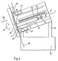
- FIG. 3 is shown in a side view a variant of the invention.
- the cutting blade 4 is formed here as a spiral blade 43.
- W the passive angle of the cutting blade 43 is described, that is, the angle within which no cutting of the food 2 by the cutting edge 42 takes place.
- the passive angle W can be larger or smaller according to the position of the knife 4 relative to the food 2, in particular if, as indicated, a diameter of the food 2 is present, which is slightly smaller than the distance between the initial knife edge 42 and the Surface of the product support 3.
- the chosen configuration of the blade 4 as a spiral blade 43, the blade shaft must not be moved to release the food 2.
- the product support 3 is formed in the illustrated embodiment as a roller belt 34.
- FIGS. 4, 5 the construction of a device 5 and a switching device 54 is shown, which causes the blade 4 and the blade hub 45 between two end positions axially, along the double arrow 55 is adjustable.
- the blade hub 45 is rotatably supported by the bearing 46.
- the hub 45 is driven by the main drive motor (not shown).
- the knife holder 44 is axially displaceable (double arrow 55) mounted in the Mesernabe 45. This can be achieved for example via plain bearing bushes.
- the knife holder 44 is driven by the knife hub 45.
- the operation of the rocker 48 to change the position of the knife via the rod 500 which is arranged at right angles to the spring element 59 of the toggle lever system and extends radially with respect to the blade axis 47.
- the spring element 59 is in this case articulated with the rod 500 connected and extends on both sides of the spring element 59.
- the rod 500 carries at its respective ends depending on a switching cam 56 which cooperates with switching elements 6.
- the longitudinal mobility of the rod 500 is indicated by the arrow 501.
- FIG. 4 are the two switching cam 56, 56 'in cooperation with the switching elements 6, 6' shown.
- the switching cam 56 is actuated by the switching element 6 such that the rod 500 is moved upward and causes a displacement of the blade 4 via the coupling rod 57 via the toggle lever system 58, 59.
- the structure of the Heidelbergelemtes 6 consists of a rotatably mounted roller 60 on a guideway 63 longitudinally displaceable (double arrow 61) angeordent.
- the drive 62 which is designed for example as an electromagnet 62.
- FIG. 4 It is shown how the lower switching element 6 'affects the pivot 502 movably mounted switching cam 56'. In the opposite position it is shown that the switching cam 56 is mounted under the roller 60. If then, if necessary, the position to be changed again, first the roller 60 'by the drive 62' back from the effective range of the switching cam 56 'retract to then control the other switching element 6, the roller 60 on the guide track 63 in the effective range of Shift cam 56 moves.
- the passive time W is indicated as an angular segment of approximately 60 °. Good can be seen that in this Winkelsegement the switching element 6 'switches the cam 56 and so moves the knife.
- the switching element 6 switches the cam 56 and so moves the knife.
- wedge principles or screw movements can be used to realize an offset of the blade 44.
- the proposed positive guidance of the knife ensures that the knife is arranged in any case when re-cutting the next disc or when blank in the defined position. In this case, additional system elements that require a complex control by the machine control, not necessary. It is also ensured by the mechanical forced operation that the movement of the knife with respect to its axial position is independent of the speed or other parameters.
Applications Claiming Priority (3)
| Application Number | Priority Date | Filing Date | Title |
|---|---|---|---|
| DE19917536 | 1999-04-19 | ||
| DE19917536A DE19917536A1 (de) | 1999-04-19 | 1999-04-19 | Aufschneidemaschine zum Aufschneiden von Lebensmittelriegeln |
| EP00107763A EP1046476B8 (de) | 1999-04-19 | 2000-04-11 | Aufschneidemaschine zum Aufschneiden von Lebensmittelriegeln |
Related Parent Applications (2)
| Application Number | Title | Priority Date | Filing Date |
|---|---|---|---|
| EP00107763.5 Division | 2000-04-11 | ||
| EP00107763A Division EP1046476B8 (de) | 1999-04-19 | 2000-04-11 | Aufschneidemaschine zum Aufschneiden von Lebensmittelriegeln |
Publications (2)
| Publication Number | Publication Date |
|---|---|
| EP1552912A1 EP1552912A1 (de) | 2005-07-13 |
| EP1552912B1 true EP1552912B1 (de) | 2012-02-29 |
Family
ID=7905015
Family Applications (2)
| Application Number | Title | Priority Date | Filing Date |
|---|---|---|---|
| EP00107763A Expired - Lifetime EP1046476B8 (de) | 1999-04-19 | 2000-04-11 | Aufschneidemaschine zum Aufschneiden von Lebensmittelriegeln |
| EP05007281A Expired - Lifetime EP1552912B1 (de) | 1999-04-19 | 2000-04-11 | Aufschneidemaschine zum Aufschneiden von Lebensmittelriegeln |
Family Applications Before (1)
| Application Number | Title | Priority Date | Filing Date |
|---|---|---|---|
| EP00107763A Expired - Lifetime EP1046476B8 (de) | 1999-04-19 | 2000-04-11 | Aufschneidemaschine zum Aufschneiden von Lebensmittelriegeln |
Country Status (5)
| Country | Link |
|---|---|
| EP (2) | EP1046476B8 (un) |
| AT (2) | ATE293521T1 (un) |
| DE (3) | DE19917536A1 (un) |
| DK (1) | DK1046476T3 (un) |
| ES (1) | ES2239955T3 (un) |
Cited By (1)
| Publication number | Priority date | Publication date | Assignee | Title |
|---|---|---|---|---|
| US8549966B2 (en) | 2007-10-22 | 2013-10-08 | Formax, Inc. | Output conveyor for a food article slicing machine |
Families Citing this family (27)
| Publication number | Priority date | Publication date | Assignee | Title |
|---|---|---|---|---|
| DE10052756A1 (de) * | 2000-03-31 | 2001-10-11 | Gebr Graef Gmbh & Co Kg | Aufschnittschneidemaschine |
| DE10147348A1 (de) * | 2001-09-26 | 2003-04-17 | Weber Maschb Gmbh & Co Kg | Vorrichtung zum Aufschneiden von Lebensmittelprodukten |
| DE10148595A1 (de) * | 2001-10-02 | 2003-04-10 | Weber Maschb Gmbh & Co Kg | Vorrichtung zum Aufschneiden von Lebensmittelprodukten |
| DE10359149A1 (de) * | 2003-12-16 | 2005-07-21 | Cfs Kempten Gmbh | Schneidspalteinstellung |
| ATE468949T1 (de) * | 2003-07-23 | 2010-06-15 | Cfs Buehl Gmbh | Axial verschiebbares messer |
| DE10333661A1 (de) * | 2003-07-23 | 2005-02-10 | Cfs Kempten Gmbh | Axial verschiebbares Messer |
| DE10333662A1 (de) * | 2003-07-23 | 2005-02-10 | Cfs Gmbh Kempten | Schneidkopf einer Exzenterschneidemaschine |
| DE102008019776A1 (de) | 2008-04-18 | 2009-10-22 | CFS Bühl GmbH | Verfahren, Vorrichtung sowie Messer zum Aufschneiden von Lebensmitteln |
| DE102009038875A1 (de) | 2009-08-26 | 2011-03-03 | Weber Maschinenbau Gmbh Breidenbach | Antriebsmotor |
| DE102009048056A1 (de) | 2009-10-02 | 2011-04-07 | CFS Bühl GmbH | Messerkopf mit integrierten Antrieben |
| DE102009056670A1 (de) | 2009-12-02 | 2011-06-09 | Weber Maschinenbau Gmbh Breidenbach | Vorrichtung zum Aufschneiden von Lebensmittelprodukten |
| ES2556634T3 (es) * | 2009-12-02 | 2016-01-19 | Weber Maschinenbau Gmbh Breidenbach | Dispositivo para cortar productos alimenticios |
| DE102010008047A1 (de) | 2010-02-16 | 2011-08-18 | Weber Maschinenbau GmbH Breidenbach, 35236 | Vorrichtung zum Aufschneiden von Lebensmittelprodukten |
| DE102010011172A1 (de) | 2010-03-12 | 2011-09-15 | Weber Maschinenbau Gmbh Breidenbach | Vorrichtung zum Aufschneiden von Lebensmittelprodukten |
| DE102009059856A1 (de) | 2009-12-21 | 2011-06-22 | Weber Maschinenbau GmbH Breidenbach, 35236 | Vorrichtung zum Aufschneiden von Lebensmittelprodukten |
| US20110179922A1 (en) | 2009-12-21 | 2011-07-28 | Weber Maschinenbau Gmbh Breidenbach | Apparatus for slicing food products |
| DE102010013893A1 (de) | 2010-04-07 | 2011-10-13 | Weber Maschinenbau Gmbh Breidenbach | Vorrichtung zum Aufschneiden von Lebensmittelprodukten |
| DE102010013892A1 (de) | 2010-04-07 | 2011-10-13 | Weber Maschinenbau Gmbh Breidenbach | Vorrichtung zum Aufschneiden von Lebensmittelprodukten |
| DE102010013891A1 (de) | 2010-04-07 | 2011-10-13 | Weber Maschinenbau Gmbh Breidenbach | Vorrichtung zum Aufschneiden von Lebensmittelprodukten |
| DE102010019744B4 (de) * | 2010-05-07 | 2020-11-26 | Weber Maschinenbau Gmbh Breidenbach | Vorrichtung zum Aufschneiden von Lebensmittelprodukten |
| US20150040521A1 (en) | 2012-01-26 | 2015-02-12 | Gea Food Solutions Germany Gmbh | Slicing into the packaging |
| DE102013206255A1 (de) | 2012-04-16 | 2013-10-17 | GEA CFS Bühl GmbH | Leerschnittrotor einer Aufschneidevorrichtung |
| DE102012207303A1 (de) | 2012-05-02 | 2013-11-07 | Weber Maschinenbau Gmbh Breidenbach | Vorrichtung zum Aufschneiden von Lebensmittelprodukten |
| DE102012207304A1 (de) | 2012-05-02 | 2013-11-21 | Weber Maschinenbau Gmbh Breidenbach | Antriebsvorrichtung |
| DE102012219594A1 (de) * | 2012-10-25 | 2014-04-30 | Textor Maschinenbau GmbH | Verfahren und Vorrichtung zum Aufschneiden von Lebensmittelprodukten |
| CN108501091B (zh) * | 2018-02-10 | 2020-05-22 | 金华市坤麦科技有限公司 | 安全性能高的香肠切花装置 |
| US11845195B2 (en) * | 2019-02-22 | 2023-12-19 | Provisur Technologies, Inc. | Pivoting blade assembly for high-speed food slicing machine |
Family Cites Families (10)
| Publication number | Priority date | Publication date | Assignee | Title |
|---|---|---|---|---|
| DE154952C (un) * | ||||
| US4523501A (en) * | 1983-09-19 | 1985-06-18 | Oscar Mayer Foods Corporation | Slicer feed mechanism |
| DE3617336A1 (de) | 1986-05-23 | 1987-11-26 | Guenther Weber | Verfahren und vorrichtung zur bildung gewichtskonstanter portionen oder stapel aus aufgeschnittenen lebensmittelprodukten |
| DE3714810A1 (de) * | 1987-05-04 | 1988-11-17 | Guenther Weber | Circularschneidemaschine |
| DE4214264C2 (de) * | 1992-05-01 | 1994-06-01 | Natec Reich Summer Gmbh Co Kg | Schneidevorrichtung zum aufschneiden von lebensmittelprodukten, insbesondere wurst, schinken, speck, fleisch, kaese und dergleichen |
| DE4402923A1 (de) | 1994-02-01 | 1995-08-03 | Dixie Union Verpackungen Gmbh | Vorrichtung zum Einlegen von Papierzetteln in Aufschnittportionen |
| DE4406868A1 (de) | 1994-03-02 | 1995-09-07 | Biforce Anstalt | Verfahren und Vorrichtung zur Bildung von Stapeln aus einzelnen Scheiben eines Lebensmittelprodukts |
| DE19518595C2 (de) * | 1995-05-20 | 1999-02-25 | Schindler & Wagner Kg | Schneidmaschine |
| DE19739788A1 (de) | 1997-09-10 | 1999-03-11 | Alpma Alpenland Masch | Schneidmesser |
| NL1009772C1 (nl) * | 1998-07-30 | 2000-02-01 | Foodcorner International B V | Werkwijze en inrichting voor het in plakken snijden van voedingswaar. |
-
1999
- 1999-04-19 DE DE19917536A patent/DE19917536A1/de not_active Withdrawn
-
2000
- 2000-04-11 ES ES00107763T patent/ES2239955T3/es not_active Expired - Lifetime
- 2000-04-11 EP EP00107763A patent/EP1046476B8/de not_active Expired - Lifetime
- 2000-04-11 DE DE20024024U patent/DE20024024U1/de not_active Expired - Lifetime
- 2000-04-11 DE DE50010076T patent/DE50010076D1/de not_active Expired - Lifetime
- 2000-04-11 AT AT00107763T patent/ATE293521T1/de not_active IP Right Cessation
- 2000-04-11 AT AT05007281T patent/ATE547217T1/de active
- 2000-04-11 DK DK00107763T patent/DK1046476T3/da active
- 2000-04-11 EP EP05007281A patent/EP1552912B1/de not_active Expired - Lifetime
Cited By (3)
| Publication number | Priority date | Publication date | Assignee | Title |
|---|---|---|---|---|
| US8549966B2 (en) | 2007-10-22 | 2013-10-08 | Formax, Inc. | Output conveyor for a food article slicing machine |
| US8850938B2 (en) | 2007-10-22 | 2014-10-07 | Formax, Inc. | Maintenance and safety system for a food article slicing machine |
| US8978529B2 (en) | 2007-10-22 | 2015-03-17 | Formax, Inc. | Food article feed apparatus for a food article slicing machine |
Also Published As
| Publication number | Publication date |
|---|---|
| ATE293521T1 (de) | 2005-05-15 |
| EP1046476A3 (de) | 2003-01-29 |
| ATE547217T1 (de) | 2012-03-15 |
| DK1046476T3 (da) | 2005-07-18 |
| EP1552912A1 (de) | 2005-07-13 |
| ES2239955T3 (es) | 2005-10-16 |
| EP1046476B1 (de) | 2005-04-20 |
| EP1046476B8 (de) | 2005-06-08 |
| DE20024024U1 (de) | 2010-05-12 |
| DE19917536A1 (de) | 2000-10-26 |
| DE50010076D1 (de) | 2005-05-25 |
| EP1046476A2 (de) | 2000-10-25 |
Similar Documents
| Publication | Publication Date | Title |
|---|---|---|
| EP1552912B1 (de) | Aufschneidemaschine zum Aufschneiden von Lebensmittelriegeln | |
| DE69608918T3 (de) | Zerkleinerungsvorrichtung | |
| EP2329930B1 (de) | Vorrichtung zum Aufschneiden von Lebensmittelprodukten | |
| EP2374583B1 (de) | Vorrichtung zum Aufschneiden von Lebensmittelprodukten | |
| EP0509230B9 (de) | Vorschubantrieb für eine Schneidemaschine zum Schneiden von Lebensmittelprodukten | |
| EP3670121B1 (de) | Schneidemaschine für strangförmiges schneidgut | |
| EP3706543B1 (de) | Schneidwerk für eine landwirtschaftliche erntemaschine | |
| DE3123183C2 (un) | ||
| DE1552696A1 (de) | Schrottzerteilschere mit verbessertem Messertraeger | |
| DE102012109003A1 (de) | Aufschnittschneidemaschine | |
| EP2374584B1 (de) | Vorrichtung zum Aufschneiden von Lebensmittelprodukten | |
| DE2208642A1 (de) | Verfahren und maschine zum zerschneiden von fleischscheiben | |
| EP2374581B1 (de) | Vorrichtung zum Aufschneiden von Lebensmittelprodukten | |
| EP3150343A1 (de) | Küchenhobel | |
| DE102010008047A1 (de) | Vorrichtung zum Aufschneiden von Lebensmittelprodukten | |
| EP3003622B1 (de) | Schere | |
| EP3166189A1 (de) | Trenn- und abisoliereinrichtung für eine kabelverarbeitungsmaschine | |
| EP1728415B1 (de) | Verfahren und Vorrichtung zum Abschneiden von Schnittgut mit einem Mähbalken | |
| DE102010019744A1 (de) | Vorrichtung zum Aufschneiden von Lebensmittelprodukten | |
| DE3020671A1 (de) | Verfahren und vorrichtung zur abtrennung von portionen von einer anzahl von saeulen aus gefrorenem fisch o.dgl. | |
| EP0745462B1 (de) | Vorrichtung zum Ablängen oder Schlitzen von kontinuierlich bewegtem, strangförmigem Material | |
| DE19905414C2 (de) | Vorrichtung zum Schneiden und Einkerben von Profilen | |
| DE2553586A1 (de) | Verfahren zum bearbeiten von fischskeletten | |
| EP2796254B1 (de) | Vorrichtung zum Positionieren oder Verstellen einer Baugruppe einer Lebensmittelverarbeitungsvorrichtung | |
| EP2724830A1 (de) | Verfahren und Vorrichtung zum Aufschneiden von Lebensmittelprodukten |
Legal Events
| Date | Code | Title | Description |
|---|---|---|---|
| PUAI | Public reference made under article 153(3) epc to a published international application that has entered the european phase |
Free format text: ORIGINAL CODE: 0009012 |
|
| AC | Divisional application: reference to earlier application |
Ref document number: 1046476 Country of ref document: EP Kind code of ref document: P |
|
| AK | Designated contracting states |
Kind code of ref document: A1 Designated state(s): AT BE CH CY DE DK ES FI FR GB GR IE IT LI LU MC NL PT SE |
|
| 17P | Request for examination filed |
Effective date: 20060113 |
|
| AKX | Designation fees paid |
Designated state(s): AT BE CH CY DE DK ES FI FR GB GR IE IT LI LU MC NL PT SE |
|
| 17Q | First examination report despatched |
Effective date: 20070219 |
|
| RAP1 | Party data changed (applicant data changed or rights of an application transferred) |
Owner name: CFS BUEHL GMBH |
|
| TPAC | Observations filed by third parties |
Free format text: ORIGINAL CODE: EPIDOSNTIPA |
|
| GRAP | Despatch of communication of intention to grant a patent |
Free format text: ORIGINAL CODE: EPIDOSNIGR1 |
|
| GRAS | Grant fee paid |
Free format text: ORIGINAL CODE: EPIDOSNIGR3 |
|
| GRAA | (expected) grant |
Free format text: ORIGINAL CODE: 0009210 |
|
| AC | Divisional application: reference to earlier application |
Ref document number: 1046476 Country of ref document: EP Kind code of ref document: P |
|
| AK | Designated contracting states |
Kind code of ref document: B1 Designated state(s): AT BE CH CY DE DK ES FI FR GB GR IE IT LI LU MC NL PT SE |
|
| REG | Reference to a national code |
Ref country code: GB Ref legal event code: FG4D Free format text: NOT ENGLISH Ref country code: CH Ref legal event code: EP |
|
| REG | Reference to a national code |
Ref country code: AT Ref legal event code: REF Ref document number: 547217 Country of ref document: AT Kind code of ref document: T Effective date: 20120315 |
|
| REG | Reference to a national code |
Ref country code: IE Ref legal event code: FG4D Free format text: LANGUAGE OF EP DOCUMENT: GERMAN |
|
| REG | Reference to a national code |
Ref country code: DE Ref legal event code: R096 Ref document number: 50016209 Country of ref document: DE Effective date: 20120426 |
|
| REG | Reference to a national code |
Ref country code: NL Ref legal event code: VDEP Effective date: 20120229 |
|
| PG25 | Lapsed in a contracting state [announced via postgrant information from national office to epo] |
Ref country code: NL Free format text: LAPSE BECAUSE OF FAILURE TO SUBMIT A TRANSLATION OF THE DESCRIPTION OR TO PAY THE FEE WITHIN THE PRESCRIBED TIME-LIMIT Effective date: 20120229 |
|
| PG25 | Lapsed in a contracting state [announced via postgrant information from national office to epo] |
Ref country code: PT Free format text: LAPSE BECAUSE OF FAILURE TO SUBMIT A TRANSLATION OF THE DESCRIPTION OR TO PAY THE FEE WITHIN THE PRESCRIBED TIME-LIMIT Effective date: 20120629 Ref country code: FI Free format text: LAPSE BECAUSE OF FAILURE TO SUBMIT A TRANSLATION OF THE DESCRIPTION OR TO PAY THE FEE WITHIN THE PRESCRIBED TIME-LIMIT Effective date: 20120229 Ref country code: GR Free format text: LAPSE BECAUSE OF FAILURE TO SUBMIT A TRANSLATION OF THE DESCRIPTION OR TO PAY THE FEE WITHIN THE PRESCRIBED TIME-LIMIT Effective date: 20120530 |
|
| REG | Reference to a national code |
Ref country code: IE Ref legal event code: FD4D |
|
| PG25 | Lapsed in a contracting state [announced via postgrant information from national office to epo] |
Ref country code: CY Free format text: LAPSE BECAUSE OF FAILURE TO SUBMIT A TRANSLATION OF THE DESCRIPTION OR TO PAY THE FEE WITHIN THE PRESCRIBED TIME-LIMIT Effective date: 20120229 |
|
| BERE | Be: lapsed |
Owner name: CFS BUHL G.M.B.H. Effective date: 20120430 |
|
| PG25 | Lapsed in a contracting state [announced via postgrant information from national office to epo] |
Ref country code: IE Free format text: LAPSE BECAUSE OF FAILURE TO SUBMIT A TRANSLATION OF THE DESCRIPTION OR TO PAY THE FEE WITHIN THE PRESCRIBED TIME-LIMIT Effective date: 20120229 Ref country code: SE Free format text: LAPSE BECAUSE OF FAILURE TO SUBMIT A TRANSLATION OF THE DESCRIPTION OR TO PAY THE FEE WITHIN THE PRESCRIBED TIME-LIMIT Effective date: 20120229 Ref country code: DK Free format text: LAPSE BECAUSE OF FAILURE TO SUBMIT A TRANSLATION OF THE DESCRIPTION OR TO PAY THE FEE WITHIN THE PRESCRIBED TIME-LIMIT Effective date: 20120229 |
|
| PG25 | Lapsed in a contracting state [announced via postgrant information from national office to epo] |
Ref country code: MC Free format text: LAPSE BECAUSE OF NON-PAYMENT OF DUE FEES Effective date: 20120430 Ref country code: IT Free format text: LAPSE BECAUSE OF FAILURE TO SUBMIT A TRANSLATION OF THE DESCRIPTION OR TO PAY THE FEE WITHIN THE PRESCRIBED TIME-LIMIT Effective date: 20120229 |
|
| REG | Reference to a national code |
Ref country code: CH Ref legal event code: PL |
|
| PLBE | No opposition filed within time limit |
Free format text: ORIGINAL CODE: 0009261 |
|
| STAA | Information on the status of an ep patent application or granted ep patent |
Free format text: STATUS: NO OPPOSITION FILED WITHIN TIME LIMIT |
|
| REG | Reference to a national code |
Ref country code: FR Ref legal event code: ST Effective date: 20121228 |
|
| GBPC | Gb: european patent ceased through non-payment of renewal fee |
Effective date: 20120529 |
|
| PG25 | Lapsed in a contracting state [announced via postgrant information from national office to epo] |
Ref country code: BE Free format text: LAPSE BECAUSE OF NON-PAYMENT OF DUE FEES Effective date: 20120430 Ref country code: LI Free format text: LAPSE BECAUSE OF NON-PAYMENT OF DUE FEES Effective date: 20120430 Ref country code: CH Free format text: LAPSE BECAUSE OF NON-PAYMENT OF DUE FEES Effective date: 20120430 |
|
| 26N | No opposition filed |
Effective date: 20121130 |
|
| PG25 | Lapsed in a contracting state [announced via postgrant information from national office to epo] |
Ref country code: FR Free format text: LAPSE BECAUSE OF NON-PAYMENT OF DUE FEES Effective date: 20120430 |
|
| REG | Reference to a national code |
Ref country code: DE Ref legal event code: R097 Ref document number: 50016209 Country of ref document: DE Effective date: 20121130 |
|
| PG25 | Lapsed in a contracting state [announced via postgrant information from national office to epo] |
Ref country code: GB Free format text: LAPSE BECAUSE OF NON-PAYMENT OF DUE FEES Effective date: 20120529 Ref country code: ES Free format text: LAPSE BECAUSE OF FAILURE TO SUBMIT A TRANSLATION OF THE DESCRIPTION OR TO PAY THE FEE WITHIN THE PRESCRIBED TIME-LIMIT Effective date: 20120609 |
|
| REG | Reference to a national code |
Ref country code: AT Ref legal event code: MM01 Ref document number: 547217 Country of ref document: AT Kind code of ref document: T Effective date: 20120411 |
|
| PG25 | Lapsed in a contracting state [announced via postgrant information from national office to epo] |
Ref country code: AT Free format text: LAPSE BECAUSE OF NON-PAYMENT OF DUE FEES Effective date: 20120411 |
|
| PG25 | Lapsed in a contracting state [announced via postgrant information from national office to epo] |
Ref country code: LU Free format text: LAPSE BECAUSE OF NON-PAYMENT OF DUE FEES Effective date: 20120411 |
|
| PGFP | Annual fee paid to national office [announced via postgrant information from national office to epo] |
Ref country code: DE Payment date: 20190418 Year of fee payment: 20 |
|
| REG | Reference to a national code |
Ref country code: DE Ref legal event code: R071 Ref document number: 50016209 Country of ref document: DE |