US8577686B2 - Method and apparatus for decoding an audio signal - Google Patents
Method and apparatus for decoding an audio signal Download PDFInfo
- Publication number
- US8577686B2 US8577686B2 US11/915,327 US91532706A US8577686B2 US 8577686 B2 US8577686 B2 US 8577686B2 US 91532706 A US91532706 A US 91532706A US 8577686 B2 US8577686 B2 US 8577686B2
- Authority
- US
- United States
- Prior art keywords
- information
- channel
- signal
- surround
- generating
- Prior art date
- Legal status (The legal status is an assumption and is not a legal conclusion. Google has not performed a legal analysis and makes no representation as to the accuracy of the status listed.)
- Active, expires
Links
Images


Classifications
-
- H—ELECTRICITY
- H04—ELECTRIC COMMUNICATION TECHNIQUE
- H04S—STEREOPHONIC SYSTEMS
- H04S1/00—Two-channel systems
- H04S1/007—Two-channel systems in which the audio signals are in digital form
-
- H—ELECTRICITY
- H04—ELECTRIC COMMUNICATION TECHNIQUE
- H04S—STEREOPHONIC SYSTEMS
- H04S3/00—Systems employing more than two channels, e.g. quadraphonic
- H04S3/008—Systems employing more than two channels, e.g. quadraphonic in which the audio signals are in digital form, i.e. employing more than two discrete digital channels
-
- H—ELECTRICITY
- H04—ELECTRIC COMMUNICATION TECHNIQUE
- H04S—STEREOPHONIC SYSTEMS
- H04S5/00—Pseudo-stereo systems, e.g. in which additional channel signals are derived from monophonic signals by means of phase shifting, time delay or reverberation
- H04S5/005—Pseudo-stereo systems, e.g. in which additional channel signals are derived from monophonic signals by means of phase shifting, time delay or reverberation of the pseudo five- or more-channel type, e.g. virtual surround
-
- G—PHYSICS
- G10—MUSICAL INSTRUMENTS; ACOUSTICS
- G10L—SPEECH ANALYSIS OR SYNTHESIS; SPEECH RECOGNITION; SPEECH OR VOICE PROCESSING; SPEECH OR AUDIO CODING OR DECODING
- G10L19/00—Speech or audio signals analysis-synthesis techniques for redundancy reduction, e.g. in vocoders; Coding or decoding of speech or audio signals, using source filter models or psychoacoustic analysis
- G10L19/008—Multichannel audio signal coding or decoding using interchannel correlation to reduce redundancy, e.g. joint-stereo, intensity-coding or matrixing
-
- H—ELECTRICITY
- H04—ELECTRIC COMMUNICATION TECHNIQUE
- H04R—LOUDSPEAKERS, MICROPHONES, GRAMOPHONE PICK-UPS OR LIKE ACOUSTIC ELECTROMECHANICAL TRANSDUCERS; DEAF-AID SETS; PUBLIC ADDRESS SYSTEMS
- H04R5/00—Stereophonic arrangements
- H04R5/04—Circuit arrangements, e.g. for selective connection of amplifier inputs/outputs to loudspeakers, for loudspeaker detection, or for adaptation of settings to personal preferences or hearing impairments
-
- H—ELECTRICITY
- H04—ELECTRIC COMMUNICATION TECHNIQUE
- H04S—STEREOPHONIC SYSTEMS
- H04S2400/00—Details of stereophonic systems covered by H04S but not provided for in its groups
- H04S2400/01—Multi-channel, i.e. more than two input channels, sound reproduction with two speakers wherein the multi-channel information is substantially preserved
-
- H—ELECTRICITY
- H04—ELECTRIC COMMUNICATION TECHNIQUE
- H04S—STEREOPHONIC SYSTEMS
- H04S2420/00—Techniques used stereophonic systems covered by H04S but not provided for in its groups
- H04S2420/01—Enhancing the perception of the sound image or of the spatial distribution using head related transfer functions [HRTF's] or equivalents thereof, e.g. interaural time difference [ITD] or interaural level difference [ILD]
-
- H—ELECTRICITY
- H04—ELECTRIC COMMUNICATION TECHNIQUE
- H04S—STEREOPHONIC SYSTEMS
- H04S2420/00—Techniques used stereophonic systems covered by H04S but not provided for in its groups
- H04S2420/03—Application of parametric coding in stereophonic audio systems
-
- H—ELECTRICITY
- H04—ELECTRIC COMMUNICATION TECHNIQUE
- H04S—STEREOPHONIC SYSTEMS
- H04S5/00—Pseudo-stereo systems, e.g. in which additional channel signals are derived from monophonic signals by means of phase shifting, time delay or reverberation
Definitions
- the present invention relates to an audio signal process, and more particularly, to method and apparatus for processing audio signals, which are capable of generating pseudo-surround signals.
- the psycho-acoustic model is a method to efficiently reduce amount of data as signals, which are not necessary in an encoding process, are removed, using a principle of human being's sound recognition manner. For example, human ears cannot recognize quiet sound immediately after loud sound, and also can hear only sound whose frequency is between 20 ⁇ 20,000 Hz.
- the present invention provides method and apparatus for decoding audio signals, which are capable of providing pseudo-surround effect in an audio system, and data structure thereof.
- a method for decoding an audio signal including extracting a downmix signal and spatial information from a received audio signal, and
- an apparatus for decoding an audio signal including a demultiplexing part extracting a downmix signal and spatial information from a received audio signal and a pseudo-surround decoding part generating a pseudo-surround signal from the downmix signal, using the spatial information.
- a data structure of an audio signal including a downmix signal which is generated by downmixing the audio signal having a plurality of channels and spatial information which is generated while the downmix signal is generated, wherein the downmix signal is converted to a pseudo-surround signal using the spatial information.
- a medium storing audio signals and having a data structure, wherein the data structure includes a downmix signal which is generated by downmixing an audio signal having a plurality of channels and spatial information which is generated while the downmixing signal is generated, the downmix signal being converted to a pseudo-surround signal with the spatial information being used.
- FIG. 1 illustrates a signal processing system according to an embodiment of the present invention
- FIG. 2 illustrates a schematic block diagram of a pseudo-surround generating part according to an embodiment of the present invention
- FIG. 3 illustrates a schematic block diagram of an information converting part according to an embodiment of the present invention
- FIG. 4 illustrates a schematic block diagram for describing a pseudo-surround rendering procedure and a spatial information converting procedure, according to an embodiment of the present invention
- FIG. 5 illustrates a schematic block diagram for describing a pseudo-surround rendering procedure and a spatial information converting procedure, according to another embodiment of the present invention
- FIG. 6 and FIG. 7 illustrate schematic block diagrams for describing channel mapping procedures according to an embodiment of the present invention
- FIG. 8 illustrates a schematic view for describing filter coefficients by channels, according to an embodiment of the present invention, through.
- FIG. 9 through FIG. 11 illustrate schematic block diagrams for describing procedures for generating surround converting information according to embodiments of the present invention.
- “Spatial information” in the present invention is indicative of information required to generate multi-channels by upmixing downmixed signal.
- the spatial parameters include a Channel Level Differences (CLDs), Inter-Channel Coherences (ICCs), and Channel Prediction Coefficients (CPCs), etc.
- the Channel Level Difference (CLD) is indicative of an energy difference between two channels.
- the Inter-Channel Coherence (ICC) is indicative of cross-correlation between two channels.
- the Channel Prediction Coefficient (CPC) is indicative of a prediction coefficient to predict three channels from two channels.
- Core codec in the present invention is indicative of a codec for coding an audio signal.
- the Core codec does not code spatial information.
- the present invention will be described assuming that a downmix audio signal is an audio signal coded by the Core codec.
- the core codec may include Moving Picture Experts Group (MPEG) Layer-II, MPEG Audio Layer-III (MP3), AC-3, Ogg Vorbis, DTS, Window Media Audio (WMA), Advanced Audio Coding (AAC) or High-Efficiency AAC (HE-AAC).
- MPEG Moving Picture Experts Group
- MP3 MPEG Audio Layer-III
- AC-3 AC-3
- Ogg Vorbis Ogg Vorbis
- DTS Digital Traffic Control
- WMA Window Media Audio
- AAC Advanced Audio Coding
- HE-AAC High-Efficiency AAC
- the core codec may not be provided. In this case, an uncompressed PCM signals is used.
- the codec may be conventional codecs and future codecs, which will be developed in the future
- Channel splitting part is indicative of a splitting part which can divide a particular number of input channels into another particular number of output channels, in which the output channel numbers are different from those of the input channels.
- the channel splitting part includes a two to three (TTT) box, which converts the two input channels to three output channels.
- the channel splitting part includes a one to two (OTT) box, which converts the one input channel to two output channels.
- TTT two to three
- OTT one to two
- the channel splitting part of the present invention is not limited by the TTT and OTT boxes, rather it will be easily appreciated that the channel splitting part may be used in systems whose input channel number and output channel number are arbitrary.
- FIG. 1 illustrates a signal processing system according to an embodiment of the present invention.
- the signal processing system includes an encoding device 100 and a decoding device 150 .
- the present invention will be described on the basis of the audio signal, it will be easily appreciated that the signal processing system of the present invention can process all signals as well as the audio signal.
- the encoding device 100 includes a downmixing part 110 , a core encoding part 120 , and a multiplexing part 130 .
- the downmixing part 110 includes a channel downmixing part 111 and a spatial information estimating part 112 .
- the downmixing part 110 When the N multi-channel audio signals X 1 , X 2 , . . . , X N are inputted the downmixing part 110 generates audio signals, depending on a certain downmixing method or an arbitrary downmix method.
- the number of the audio signals outputted from the downmixing part 110 to the core encoding part 120 is less than the number “N” of the input multi-channel audio signals.
- the spatial information estimating part 112 extracts spatial information from the input multi-channel audio signals, and then transmits the extracted spatial information to the multiplexing part 130 .
- the number of the downmix channel may one or two, or be a particular number according to downmix commands.
- the number of the downmix channels may be set.
- an arbitrary downmix signal is optionally used as the downmix audio signal.
- the core encoding part 120 encodes the downmix audio signal which is transmitted through the downmix channel.
- the encoded downmix audio signal is inputted to the multiplexing part 130 .
- the multiplexing part 130 multiplexes the encoded downmix audio signal and the spatial information to generate a bitstream, and then transmits the generated a bitstream to the decoding device 150 .
- the bitstream may include a core codec bitstream and a spatial information bitstream.
- the decoding device 150 includes a demultiplexing part 160 , a core decoding part 170 , and a pseudo-surround decoding part 180 .
- the pseudo-surround decoding part 180 may include a pseudo surround generating part 200 and an information converting part 300 .
- the decoding device 150 may further include a spatial information decoding part 190 .
- the demultiplexing part 160 receives the bitstream and demultiplexes the received bitstream to a core codec bitstream and a spatial information bitstream.
- the demultiplexing part 160 extracts a downmix signal and spatial information from the received bitstream.
- the core decoding part 170 receives the core codec bitstream from the demultiplexing part 160 to decode the received bitstream, and then outputs the decoding result as the decoded downmix signals to the pseudo-surround decoding part 180 .
- the decoded downmix signal may be the mono-channel signal or the stereo-channel signal.
- the spatial information decoding part 190 receives the spatial information bitstream from the demultiplexing part 160 , decodes the spatial information bitstream, and output the decoding result as the spatial information.
- the pseudo-surround decoding part 180 serves to generate a pseudo-surround signal from the downmix signal using the spatial information.
- the following is a description for the pseudo-surround generating part 200 and the information converting part 300 , which are included in the pseudo-surround decoding part 180 .
- the information converting part 300 receives spatial information and filter information. Also, the information converting part 300 generates surround converting information using the spatial information and the filter information. Here, the generated surround converting information has the pattern which is fit to generate the pseudo-surround signal.
- the surround converting information is indicative of a filter coefficient in a case that the pseudo-surround generating part 200 is a particular filter.
- the filter coefficient used as the surround converting information, it will be easily appreciated that the surround converting information is not limited by the filter coefficient.
- the filter information is assumed to be head-related transfer function (HRTF), it will be easily appreciated that the filter information is not limited by the HRTF.
- HRTF head-related transfer function
- the above-described filter coefficient is indicative of the coefficient of the particular filter.
- the filter coefficient may be defined as follows.
- a proto-type HRTF filter coefficient is indicative of an original filter coefficient of a particular HRTF filter, and may be expressed as GL_L, etc.
- a converted HRTF filter coefficient is indicative of a filter coefficient converted from the proto-type HRTF filter coefficient, and may be expressed as GL_L′, etc.
- a spatialized HRTF filter coefficient is a filter coefficient obtained by spatializing the proto-type HRTF filter coefficient to generate a pseudo-surround signal, and may be expressed as FL_L 1 , etc.
- a master rendering coefficient is indicative of a filter coefficient which is necessary to perform rendering, and may be expressed as HL_L, etc.
- An interpolated master rendering coefficient is indicative of a filter coefficient obtained by interpolating and/or blurring the master rendering coefficient, and may be expressed as HL_L′, etc. According to the present invention, it will be easily appreciated that filter coefficients do not limit by the above filter coefficients.
- the pseudo-surround generating part 200 receives the decoded downmix signal from the core decoding part 170 , and the surround converting information from the information converting part 300 , and generates a pseudo-surround signal, using the decoded downmix signal and the surround converting information.
- the pseudo-surround signal serves to provide a virtual multi-channel (or surround) sound in a stereo audio system.
- the pseudo-surround signal will play the above role in any devices as well as in the stereo audio system.
- the pseudo-surround generating part 200 may perform various types of rendering according to setting modes.
- the decoding device 150 including the pseudo-surround decoding part 180 may provide the effect that users have a virtual stereophonic listening experience, although the output channel of the device 150 is a stereo channel instead of a multi-channel.
- an audio signal structure 140 When the audio signal is transmitted on the basis of a payload, it may be received through each channel or a single channel.
- An audio payload of 1 frame is composed of a coded audio data field and an ancillary data field.
- the ancillary data field may include coded spatial information. For example, if a data rate of an audio payload is at 48 ⁇ 128 kbps, the data rate of spatial information may be at 5 ⁇ 32 kbps. Such an example will not limit the scope of the present invention.
- FIG. 2 illustrates a schematic block diagram of a pseudo-surround generating part 200 according to an embodiment of the present invention.
- Domains described in the present invention include a downmix domain in which a downmix signal is decoded, a spatial information domain in which spatial information is processed to generate surround converting information, a rendering domain in which a downmix signal undergoes rendering using spatial information, and an output domain in which a pseudo-surround signal of time domain is output.
- the output domain audio signal can be heard by humans.
- the output domain means a time domain.
- the pseudo-surround generating part 200 includes a rendering part 220 and an output domain converting part 230 .
- the pseudo-surround generating part 200 may further include a rendering domain converting part 210 which converts a downmix domain into a rendering domain when the downmix domain is different from the rendering domain.
- the rendering domain is set as a subband domain
- the rendering domain may be set as any domain.
- a first domain conversion method a time domain is converted to the rendering domain in case that the downmix domain is the time domain.
- a discrete frequency domain is converted to the rendering domain in case that the downmix domain is the discrete frequency domain.
- a third downmix conversion method a discrete frequency domain is converted to the time domain and then, the converted time domain is converted into the rendering domain in case that the downmix domain is a discrete frequency domain.
- the rendering part 220 performs pseudo-surround rendering for a downmix signal using surround converting information to generate a pseudo-surround signal.
- the pseudo-surround signal output from the pseudo-surround decoding part 180 with the stereo output channel becomes a pseudo-surround stereo output having virtual surround sound.
- the pseudo-surround signal outputted from the rendering part 220 is a signal in the rendering domain, domain conversion is needed when the rendering domain is not a time domain.
- a pseudo-surround rendering method may be implemented by HRTF filtering method, in which input signal undergoes a set of HRTF filters.
- spatial information may be a value which can be used in a hybrid filterbank domain which is defined in MPEG surround.
- the pseudo-surround rendering method can be implemented as the following embodiments, according to types of downmix domain and spatial information domain. To this end, the downmix domain and the spatial information domain are made to be coincident with the rendering domain.
- pseudo-surround rendering method there is a method in which pseudo-surround rendering for a downmix signal is performed in a subband domain (QMF).
- the subband domain includes a simple subband domain and a hybrid domain.
- the rendering domain converting part 210 converts the downmix domain into the subband domain.
- the downmix domain is subband domain, the downmix domain does not need to be converted.
- the output domain converting part 230 converts the rendering domain into time domain.
- the discrete frequency domain is indicative of a frequency domain except for a subband domain. That is, the frequency domain may include at least one of the discrete frequency domain and the subband domain.
- the rendering domain converting part 210 converts the downmix domain into the discrete frequency domain.
- the spatial information domain is a subband domain
- the spatial information domain needs to be converted to a discrete frequency domain.
- the method serves to replace filtering in a time domain with operations in a discrete frequency domain, such that operation speed may be relatively rapidly performed.
- the output domain converting part 230 may convert the rendering domain into time domain.
- the pseudo-surround rendering method there is a method in which pseudo-surround rendering for a downmix signal is performed in a time domain.
- the rendering domain converting part 210 converts the downmix domain into the time domain.
- spatial information domain is a subband domain
- the spatial information domain is also converted into the time domain.
- the output domain converting part 230 does not need to convert the rendering domain into time domain.
- FIG. 3 illustrates a schematic block diagram of an information converting part 300 according to an embodiment of the present invention.
- the information converting part 300 includes a channel mapping part 310 , a coefficient generating part 320 , and an integrating part 330 .
- the information converting part 300 may further include an additional processing part (not shown) for additionally processing filter coefficients and/or a rendering domain converting part 340 .
- the channel mapping part 310 performs channel mapping such that the inputted spatial information may be mapped to at least one channel signal of multi-channel signals, and then generates channel mapping output values as channel mapping information.
- the coefficient generating part 320 generates channel coefficient information.
- the channel coefficient information may include coefficient information by channels or interchannel coefficient information.
- the coefficient information by channels is indicative of at least one of size information, and energy information, etc.
- the interchannel coefficient information is indicative of interchannel correlation information which is calculated using a filter coefficient and a channel mapping output value.
- the coefficient generating part 320 may include a plurality of coefficient generating parts by channels.
- the coefficient generating part 320 generates the channel coefficient information using the filter information and the channel mapping output value.
- the channel may include at least one of multi-channel, a downmix channel, and an output channel. From now, the channel will be described as the multi-channel, and the coefficient information by channels will be also described as size information.
- the coefficient generating part 320 may generate the channel coefficient information, according to the channel number or other characteristics.
- the integrating part 330 receiving coefficient information by channels integrates or sums up the coefficient information by channels to generate integrating coefficient information. Also, the integrating part 330 generates filter coefficients using the integrating coefficients of the integrating coefficient information. The integrating part 330 may generate the integrating coefficients by further integrating additional information with the coefficients by channels. The integrating part 330 may integrate coefficients by at least one channel, according to characteristics of channel coefficient information. For example, the integrating part 330 may perform integrations by downmix channels, by output channels, by one channel combined with output channels, and by combination of the listed channels, according to characteristics of channel coefficient information. In addition, the integrating part 330 may generate additional process coefficient information by additionally processing the integrating coefficient.
- the integrating part 330 may generate a filter coefficient by the additional process.
- the integrating part 330 may generate filter coefficients by additionally processing the integrating coefficient such as by applying a particular function to the integrating coefficient or by combining a plurality of integrating coefficients.
- the integration coefficient information is at least one of output channel magnitude information, output channel energy information, and output channel correlation information.
- the rendering domain converting part 340 may coincide the spatial information domain with the rendering domain.
- the rendering domain converting part 340 may convert the domain of filter coefficients for the pseudo-surround rendering, into the rendering domain.
- a coefficient set to be applied to left and right downmix signals is generated, in generating coefficient information by channels.
- a set of filter coefficients may include filter coefficients, which are transmitted from respective channels to their own channels, and filter coefficients, which are transmitted from respective channels to their opposite channels.
- FIG. 4 illustrates a schematic block diagram for describing a pseudo-surround rendering procedure and a spatial information converting procedure, according to an embodiment of the present invention. Then, the embodiment illustrates a case where a decoded stereo downmix signal is received to a pseudo-surround generating part 410 .
- An information converting part 400 may generate a coefficient which is transmitted to its own channel in the pseudo-surround generating part 410 , and a coefficient which is transmitted to an opposite channel in the pseudo-surround generating part 410 .
- the information converting part 400 generates a coefficient HL_L and a coefficient HL_R, and output the generated coefficients HL_L and HL_R to a first rendering part 413 .
- the coefficient HL_L is transmitted to a left output side of the pseudo-surround generating part 410
- the coefficient HL_R is transmitted to a right output side of the pseudo-surround generating part 410 .
- the information converting part 400 generates coefficients HR_R and HR_L, and output the generated coefficients HR_R and HR_L to a second rendering part 414 .
- the coefficient HR_R is transmitted to a right output side of the pseudo-surround generating part 410
- the coefficient HR_L is transmitted to a left output side of the pseudo-surround generating part 410 .
- the pseudo-surround generating part 410 includes the first rendering part 413 , the second rendering part 414 , and adders 415 and 416 . Also, the pseudo-surround generating part 410 may further include domain converting parts 411 and 412 which coincide downmix domain with rendering domain, when two domains are different from each other, for example, when a downmix domain is not a subband domain, and a rendering domain is the subband domain. Here, the pseudo-surround generating part 410 may further include inverse domain converting parts 417 and 418 which covert a rendering domain, for example, subband domain to a time domain. Therefore, users can hear audio with a virtual multi-channel sound through ear phones having stereo channels, etc.
- the first and second rendering parts 413 and 414 receive stereo downmix signals and a set of filter coefficients.
- the set of filter coefficients are applied to left and right downmix signals, respectively, and are outputted from an integrating part 403 .
- the first and second rendering parts 413 and 414 perform rendering to generate pseudo-surround signals from a downmix signal using four filter coefficients, HL_L, HL_R, HR_L, and HR_R.
- the first rendering part 413 may perform rendering using the filter coefficient HL_L and HL_R, in which the filter coefficient HL_L is transmitted to its own channel, and the filter coefficient HL_R is transmitted to a channel opposite to its own channel.
- the first rendering part 413 may include sub-rendering parts (not shown) 1 - 1 and 1 - 2 .
- the sub-rendering part 1 - 1 performs rendering using a filter coefficient HL_L which is transmitted to a left output side of the pseudo-surround generating part 410
- the sub-rendering part 1 - 2 performs rendering using a filter coefficient HL_R which is transmitted to a right output side of the pseudo-surround generating part 410 .
- the second rendering part 414 performs rendering using the filter coefficient sets HR_R and HR_L, in which the filter coefficient HR_R is transmitted to its own channel, and the filter coefficient HR_L is transmitted to a channel opposite to its own channel.
- the second rendering part 414 may include sub-rendering parts (not shown) 2 - 1 and 2 - 2 .
- the sub-rendering part 2 - 1 performs rendering using a filter coefficient HR_R which is transmitted to a right output side of the pseudo-surround generating part 410
- the sub-rendering part 2 - 2 performs rendering using a filter coefficient HR_L which is transmitted to a left output side of the pseudo-surround generating part 410 .
- the HL_R and HR_R are added in the adder 416 , and the HL_L and HR_L are added in the adder 415 .
- the HL_R and HR_L become zero, which means that a coefficient of cross terms be zero.
- two other passes do not affect each other.
- rendering may be performed by an embodiment having structure similar to that of FIG. 4 . More specifically, an original mono input is referred to as a first channel signal, and a signal obtained by decorrelating the first channel signal is referred as a second channel signal.
- the first and second rendering parts 413 and 414 may receive the first and second channel signals and perform renderings of them.
- Equation 1 is expressed on the basis of the proto-type HRTF filter coefficient.
- G must be replaced with G′ in the following Equations.
- the temporary multi-channel signal “p” may be expressed by the product of a channel mapping coefficient “D” by a stereo downmix signal “x” as the following Equation 2.
- Equation 5 the output signal “y” and the stereo downmix signal “x” have a relationship as following Equation 5.
- H [ HL_L HR_L HL_R HR_R ]
- y Hx [ Equation ⁇ ⁇ 5 ]
- the product of the filter coefficients allows “H” to be obtained.
- the output signal “y” may be acquired by multiplying the stereo downmix signal “x” and the “H”.
- Coefficient F (FL_L 1 , FL_L 2 , . . . ), will be described later, may be obtained by following Equation 6.
- FIG. 5 illustrates a schematic block diagram for describing a pseudo-surround rendering procedure and a spatial information converting procedure, according to another embodiment of the present invention. Then, the embodiment illustrates a case where a decoded mono downmix signal is received to a pseudo-surround generating part 510 .
- an information converting part 500 includes a channel mapping part 501 , a coefficient generating part 502 , and an integrating part 503 . Since such elements of the information converting part 500 perform the same functions as those of the information converting part 400 of FIG. 4 , their detailed descriptions will be omitted below.
- the information converting part 500 may generate a final filter coefficient whose domain is coincided to the rendering domain in which pseudo-surround rendering is performed.
- the filter coefficient set may include filter coefficient sets HM_L and HM_R.
- the filter coefficient HM_L is used to perform rendering of the mono downmix signal to output the rendering result to the left channel of the pseudo-surround generating part 510 .
- the filter coefficient HM_R is used to perform rendering of the mono downmix signal to output the rendering result to the right channel of the pseudo-surround generating part 510 .
- the pseudo-surround generating part 510 includes a third rendering part 512 . Also, the pseudo-surround generating part 510 may further include a domain converting part 511 and inverse domain converting parts 513 and 514 . The elements of the pseudo-surround generating part 510 are different from those of the pseudo-surround generating part 410 of FIG. 4 in that, since the decoded downmix signal is a mono downmix signal in FIG. 5 , the pseudo-surround generating part 510 includes one third rendering part 512 performing pseudo-surround rendering and one domain converting part 511 .
- the third rendering part 512 receives a filter coefficient set HM_L and HM_R from the integrating part 503 , and may perform pseudo-surround rendering of the mono downmix signal using the received filter coefficient, and generate a pseudo-surround signal.
- an output of stereo downmix can be obtained by performing pseudo-surround rendering of mono downmix signal, according to the following two methods.
- the third rendering part 512 (for example, a HRTF filter) does not use a filter coefficient for a pseudo-surround sound but uses a value used when processing stereo downmix.
- the output of stereo downmix having a desired channel number is obtained.
- the input mono downmix signal is denoted by “x”
- a channel mapping coefficient is denoted by “D”
- a prototype HRTF filter coefficient of an external input is denoted by “G”
- a temporary multi-channel signal is denoted by “p”
- an output signal which has undergone rendering is denoted by “y”
- the notations “x”, “D”, “G”, “p”, and “y” may be expressed by a matrix form as following Equation 7.
- x ⁇ [ Mi ]
- p ⁇ [ L Ls R Rs C LFE ]
- D ⁇ [ D_L D_Ls D_R D_Rs D_C D_LFE ]
- G ⁇ [ GL_L GLs_L GR_L GRs_L GC_L GLFE_L GL_R GLs_R GR_R GRs_R GC_R GLFE_R ]
- y ⁇ [ Lo Ro ] [ Equation ⁇ ⁇ 7 ]
- FIG. 4 illustrates a case where the stereo downmix signal is received
- FIG. 5 illustrates a case where the mono downmix signal is received.
- FIG. 6 and FIG. 7 illustrate schematic block diagrams for describing channel mapping procedures according to embodiments of the present invention.
- the channel mapping process means a process in which at least one of channel mapping output values is generated by mapping the received spatial information to at least one channel of multi channels, to be compatible with the pseudo-surround generating part.
- the channel mapping process is performed in the channel mapping parts 401 and 501 .
- spatial information for example, energy
- an Lfe channel and a center channel C may not be splitted. In this case, since such a process does not need a channel splitting part 604 or 705 , it may simplify calculations.
- channel mapping output values may be generated using coefficients, CLD 1 through CLD 5 , ICC 1 through ICC 5 , etc.
- the channel mapping output values may be D L , D R , D C , D LEF , D Ls , D Rs , etc. Since the channel mapping output values are obtained by using spatial information, various types of channel mapping output values may be obtained according to various formulas.
- the generation of the channel mapping output values may be varied according to tree configuration of spatial information received by a decoding device 150 , and a range of spatial information which is used in the decoding device 150 .
- FIGS. 6 and 7 illustrate schematic block diagrams for describing channel mapping structures according to an embodiment of the present invention.
- a channel mapping structure may include at least one channel splitting part indicative of an OTT box.
- the channel structure of FIG. 6 has 5151 configuration.
- multi-channel signals L, R, C, LFE, Ls, Rs may be generated from the downmix signal “m”, using the OTT boxes 601 , 602 , 603 , 604 , 605 and spatial information, for example, CLD 0 , CLD 1 , CLD 2 , CLD 3 , CLD 4 , ICC 0 , ICC 1 , ICC 2 , ICC 3 , etc.
- the channel mapping output values may be obtained, using CLD only, as shown in Equation 8.
- multi-channel signals L, Ls, R, Rs, C, LFE may be generated from the downmix signal “m”, using the OTT boxes 701 , 702 , 703 , 704 , 705 and spatial information, for example, CLD 0 , CLD 1 , CLD 2 , CLD 3 , CLD 4 , ICC 0 , ICC 1 , ICC 3 , ICC 4 , etc.
- the channel mapping output values may be obtained, using CLD only, as shown in Equation 9.
- the channel mapping output values may be varied, according to frequency bands, parameter bands and/or transmitted time slots.
- distortion may occur when performing pseudo-surround rendering.
- blurring of the channel mapping output values in the frequency and time domains may be needed.
- the method to prevent the distortion is as follows. Firstly, the method may employ frequency blurring and time blurring, or also any other technique which is suitable for pseudo-surround rendering. Also, the distortion may be prevented by multiplying each channel mapping output value by a particular gain.
- FIG. 8 illustrates a schematic view for describing filter coefficients by channels, according to an embodiment of the present invention.
- the filter coefficient may be a HRTF coefficient.
- a signal from a left channel source “L” 810 is filtered by a filter having a filter coefficient GL_L, and then the filtering result L*GL_L is transmitted as the left output.
- a signal from the left channel source “L” 810 is filtered by a filter having a filter coefficient GL_R, and then the filtering result L*GL_R is transmitted as the right output.
- the left and right outputs may attain to left and right ears of user, respectively.
- all left and right outputs are obtained by channels. Then, the obtained left outputs are summed to generate a final left output (for example, Lo), and the obtained right outputs are summed to generate a final right output (for example, Ro).
- Equation 10 the final left and right outputs which have undergone pseudo-surround rendering may be expressed by following Equation 10.
- Lo L*GL — L+C*GC — L+R*GR — L+Ls*GLs — L+Rs*GRs — L
- Ro L*GL — R+C*GC — R+R*GR — R+Ls*GLs — R+Rs*GRs — R [Equation 10]
- the method for obtaining L( 810 ), C( 800 ), R( 820 ), Ls( 830 ), and Rs( 840 ) is as follows.
- L( 810 ), C( 800 ), R( 820 ), Ls( 830 ), and Rs( 840 ) may be obtained by a decoding method for generating multi-channel signal using a downmix signal and spatial information.
- the multi-channel signal may be generated by an MPEG surround decoding method.
- L( 810 ), C( 800 ), R( 820 ), Ls( 830 ), and Rs( 840 ) may be obtained by equations related to only spatial information.
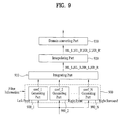
- FIG. 9 through FIG. 11 illustrate schematic block diagrams for describing procedures for generating surround converting information, according to embodiments of the present invention.
- FIG. 9 illustrates a schematic block diagram for describing procedures for generating surround converting information according to an embodiment of the present invention.
- an information converting part may include a coefficient generating part 900 and an integrating part 910 .
- the coefficient generating part 900 includes at least one of sub coefficient generating parts (coef_ 1 generating part 900 _ 1 , coef_ 2 generating part 900 _ 2 , . . . , coef_N generating part 900 _N).
- the information converting part may further include an interpolating part 920 and a domain converting part 930 so as to additionally processing filter coefficients.
- the coefficient generating part 900 generates coefficients, using spatial information and filter information.
- the following is a description for the coefficient generation in a particular sub coefficient generating part for example, coef_ 1 generating part 900 _ 1 , which is referred to as a first sub coefficient generating part.
- the first sub coefficient generating part 900 _ 1 when a mono downmix signal is input, the first sub coefficient generating part 900 _ 1 generates coefficients FL_L and FL_R for a left channel of the multi channels, using a value D_L which is generated from spatial information.
- the generated coefficients FL_L and FL_R may be expressed by following Equation 11.
- FL — L D — L*GL — L (a coefficient used for generating the left output from input mono downmix signal)
- FL — R D — L*GL — R (a coefficient used for generating the right output from input mono channel signal) [Equation 11]
- the D_L is a channel mapping output value generated from the spatial information in the channel mapping process. Processes for obtaining the D_L may be varied, according to tree configuration information which an encoding device transmits and a decoding device receives.
- the coef_ 2 generating part 900 _ 2 is referred to as a second sub coefficient generating part and the coef_ 3 generating part 900 _ 3 is referred to as a third sub coefficient generating part
- the second sub coefficient generating part 900 _ 2 may generate coefficients FR_L and FR_R
- the third sub coefficient generating part 900 _ 3 may generate FC_L and FC_R, etc.
- the first sub coefficient generating part 900 _ 1 when the stereo downmix signal is input, the first sub coefficient generating part 900 _ 1 generates coefficients FL_L 1 , FL_L 2 , FL_R 1 , and FL_R 2 for a left channel of the multi channel, using values D_L 1 and D_L 2 which are generated from spatial information.
- the generated coefficients FL_L 1 , FL_L 2 , FL_R 1 , and FL_R 2 may be expressed by following Equation 12.
- FL — L 1 D — L 1 *GL — L (a coefficient used for generating the left output from a left downmix signal of the input stereo downmix signal)
- FL — L 2 D — L 2 *GL — L (a coefficient used for generating the left output from a right downmix signal of the input stereo downmix signal)
- FL — R 1 D — L*GL — R (a coefficient used for generating the right output from a left downmix signal of the input stereo downmix signal)
- FL — R 2 D — L 2 *GL — R (a coefficient used for generating the right output from a right downmix signal of the input stereo downmix signal) [Equation 12)
- a plurality of coefficients may be generated by at least one of coefficient generating parts 900 _ 1 through 900 _N when the stereo downmix signal is input.
- the integrating part 910 generates filter coefficients by integrating coefficients, which are generated by channels.
- the integration of the integrating part 910 for the cases that mono and stereo downmix signals are input may be expressed by following Equation 13.
- HM — L FL — L+FR — L+FC — L+FLS — L+FRS — L+FLFE — L
- HM — R FL — R+FR — R+FC — R+FLS — R+FRS — R+FLFE — R
- the HM_L and HM_R are indicative of filter coefficients for pseudo-surround rendering in case the mono downmix signal is input.
- the HL_L, HR_L, HL_R, and HR_R are indicative of filter coefficients for pseudo-surround rendering in case the stereo downmix signal is input.
- the interpolating part 920 may interpolate the filter coefficients. Also, time blurring of filter coefficients may be performed as post processing. The time blurring may be performed in a time blurring part (not shown).
- the interpolating part 920 interpolates the filter coefficients to obtain spatial information which does not exist between the transmitted and generated spatial information. For example, when spatial information exists in n-th parameter slot and n+K-th parameter slot (K>1), an embodiment of linear interpolation may be expressed by following Equation 14. In the embodiment of Equation 14, spatial information in a parameter slot which was not transmitted may be obtained using the generated filter coefficients, for example, HL_L, HR_L, HL_R and HR_R. It will be appreciated that the interpolating part 920 may interpolate the filter coefficients by various ways.
- HM — L ( n+j ) HM — L ( n )* a+HM — L ( n+k )*(1 ⁇ a )
- HM — R ( n+j ) HM — R ( n )* a+HM — R ( n+k )*(1 ⁇ a )
- HM_L(n+j) and HM_R(n+j) are indicative of coefficients obtained by interpolating filter coefficient for pseudo-surround rendering, when a mono downmix signal is input.
- HL_L(n+j), HR_L(n+j), HL_R(n+j) and HR_R(n+j) are indicative of coefficients obtained by interpolating filter coefficient for pseudo-surround rendering, when a stereo downmix signal is input.
- ‘j’ and ‘k’ are integers, 0 ⁇ j ⁇ k.
- spatial information in a parameter slot, which was not transmitted, between n-th and n+K-th parameter slots may be obtained using spatial information in the n-th and n+K-th parameter slots.
- the unknown value of spatial information may be obtained on a straight line formed by connecting values of spatial information in two parameter slots, according to Equation 15.
- Discontinuous point can be generated when the coefficient values between adjacent blocks in a time domain are rapidly changed. Then, time blurring may be performed by the time blurring part to prevent distortion caused by the discontinuous point.
- the time blurring operation may be performed in parallel with the interpolation operation. Also, the time blurring and interpolation operations may be differently processed according to their operation order.
- HM — L ( n )′ HM — L ( n )* b+HM — L ( n ⁇ 1)′*(1 ⁇ b )
- HM — R ( n )′ HM — R ( n )* b+HM — R ( n ⁇ 1)′*(1 ⁇ b )
- Equation 16 Equation 16
- Equation 16 describes blurring through a 1-pole IIR filter, in which the blurring results may be obtained, as follows. That is, the filter coefficients HM_L(n) and HM_R(n) in the present block (n) are multiplied by “b”, respectively. And then, the filter coefficients HM_L(n ⁇ 1)′ and HM_R(n ⁇ 1)′ in the previous block (n ⁇ 1) are multiplied by (1 ⁇ b), respectively. The multiplying results are added as shown in Equation 16.
- “b” is a constant (0 ⁇ b ⁇ 1). The smaller the value of “b” the more the blurring effect is increased. On the contrary, the larger the value of “b”, the less the blurring effect is increased. Similar to the above methods, the blurring of remaining filter coefficients may be performed.
- Equation 16 interpolation and blurring may be expressed by an Equation 17.
- HM — L ( n+j )′ ( HM — L ( n )* a+HM — L ( n+k )*(1 ⁇ a ))* b+HM — L ( n+j ⁇ 1)′*(1 ⁇ b )
- the domain converting part 930 converts the spatial information domain into the rendering domain. However, if the rendering domain coincides with the spatial information domain, such domain conversion is not needed.
- a spatial information domain is a subband domain and a rendering domain is a frequency domain
- such domain conversion may involve processes in which coefficients are extended or reduced to comply with a range of frequency and a range of time for each subband.
- FIG. 10 illustrates a schematic block diagram for describing procedures for generating surround converting information according to another embodiment of the present invention.
- an information converting part may include a coefficient generating part 1000 and an integrating part 1020 .
- the coefficient generating part 1000 includes at least one of sub coefficient generating parts (coef_ 1 generating part 1000 _ 1 , coef_ 2 generating part 1000 _ 2 , and coef_N generating part 1000 _N).
- the information converting part may further include an interpolating part 1010 and a domain converting part 1030 so as to additionally process filter coefficients.
- the interpolating part 1010 includes at least one of sub interpolating parts 1010 _ 1 , 1010 _ 2 , . . . , and 1010 _N. Unlike the embodiment of FIG. 9 , in the embodiment of FIG. 10 the interpolating part 1010 interpolates respective coefficients which the coefficient generating part 1000 generates by channels. For example, the coefficient generating part 1000 generates coefficients FL_L and FL_R in case of a mono downmix channel and coefficients FL_L 1 , FL_L 2 , FL_R 1 and FL_R 2 in case of a stereo downmix channel.
- FIG. 11 illustrates a schematic block diagram for describing procedures for generating surround converting information according to still another embodiment of the present invention. Unlike embodiments of FIGS. 9 and 10 , in the embodiment of FIG. 11 an interpolating part 1100 interpolates respective channel mapping output values, and then coefficient generating part 110 generates coefficients by channels using the interpolation results.
- the processes such as filter coefficient generation are performed in frequency domain, since channel mapping output values are in the frequency domain (for example, a parameter band unit has a single value). Also, when pseudo-surround rendering is performed in a subband domain, the domain converting part 930 or 1030 does not perform domain conversion, but bypasses filter coefficients of the subband domain, or may perform conversion to adjust frequency resolution, and then output the conversion result.
- the present invention may provide an audio signal having a pseudo-surround sound in a decoding apparatus, which receives an audio bitstream including downmix signal and spatial information of the multi-channel signal, even in environments where the decoding apparatus cannot generate the multi-channel signal.
Abstract
Description
y=G·p [Equation 3]
y==GDx [Equation 4]
Lo=L*GL — L+C*GC — L+R*GR — L+Ls*GLs — L+Rs*GRs — L
Ro=L*GL — R+C*GC — R+R*GR — R+Ls*GLs — R+Rs*GRs — R [Equation 10]
FL — L=D — L*GL — L (a coefficient used for generating the left output from input mono downmix signal)
FL — R=D — L*GL — R (a coefficient used for generating the right output from input mono channel signal) [Equation 11]
FL — L1=D — L1*GL — L (a coefficient used for generating the left output from a left downmix signal of the input stereo downmix signal)
FL — L2=D — L2*GL — L (a coefficient used for generating the left output from a right downmix signal of the input stereo downmix signal)
FL — R1=D — L*GL — R (a coefficient used for generating the right output from a left downmix signal of the input stereo downmix signal)
FL — R2=D — L2*GL — R (a coefficient used for generating the right output from a right downmix signal of the input stereo downmix signal) [Equation 12)
HM — L=FL — L+FR — L+FC — L+FLS — L+FRS — L+FLFE — L
HM — R=FL — R+FR — R+FC — R+FLS — R+FRS — R+FLFE — R
HL — L=FL — L1+FR — L1+FC — L1+FLS — L1+FRS — L1+FLFE — L1
HR — L=FL — L2+FR — L2+FC — L2+FLS — L2+FRS — L2+FLFE — L2
HL — R=FL — R1+FR — R1+FC — R1+FLS — R1+FRS — R1+FLFE — R1
HR — R=FL — R2+FR — R2+FC — R2+FLS — R2+FRS — R2+FLFE — R2 [Equation 13]
HM — L(n+j)=HM — L(n)*a+HM — L(n+k)*(1−a)
HM — R(n+j)=HM — R(n)*a+HM — R(n+k)*(1−a)
HL — L(n+j)=HL — L(n)*a+HL — L(n+k)*(1−a)
HR — L(n+j)=HR — L(n)*a+HR — L(n+k)*(1−a)
HL — R(n+j)=HL — R(n)*a+HL — R(n+k)*(1−a)
HR — R(n+j)=HR — R(n)*a+HR — R(n+k)*(1−a) [Equation 14]
a=j/k [Equation 15]
HM — L(n)′=HM — L(n)*b+HM — L(n−1)′*(1−b)
HM — R(n)′=HM — R(n)*b+HM — R(n−1)′*(1−b) [Equation 16]
HM — L(n+j)′=(HM — L(n)*a+HM — L(n+k)*(1−a))*b+HM — L(n+j−1)′*(1−b)
HM — R(n+j)′−(HM — R(n)*a+HM — R(n+k)*(1−a))*b+HM — R(n+j−1)′*(1−b) [Equation 17]
Claims (14)
Priority Applications (1)
| Application Number | Priority Date | Filing Date | Title |
|---|---|---|---|
| US11/915,327 US8577686B2 (en) | 2005-05-26 | 2006-05-25 | Method and apparatus for decoding an audio signal |
Applications Claiming Priority (10)
| Application Number | Priority Date | Filing Date | Title |
|---|---|---|---|
| US68457905P | 2005-05-26 | 2005-05-26 | |
| US75998006P | 2006-01-19 | 2006-01-19 | |
| US77672406P | 2006-02-27 | 2006-02-27 | |
| US77944206P | 2006-03-07 | 2006-03-07 | |
| US77941706P | 2006-03-07 | 2006-03-07 | |
| US77944106P | 2006-03-07 | 2006-03-07 | |
| KR1020060030670A KR20060122695A (en) | 2005-05-26 | 2006-04-04 | Method and apparatus for decoding audio signal |
| KR10-2006-0030670 | 2006-04-04 | ||
| US11/915,327 US8577686B2 (en) | 2005-05-26 | 2006-05-25 | Method and apparatus for decoding an audio signal |
| PCT/KR2006/001986 WO2006126843A2 (en) | 2005-05-26 | 2006-05-25 | Method and apparatus for decoding audio signal |
Publications (2)
| Publication Number | Publication Date |
|---|---|
| US20080294444A1 US20080294444A1 (en) | 2008-11-27 |
| US8577686B2 true US8577686B2 (en) | 2013-11-05 |
Family
ID=37452464
Family Applications (3)
| Application Number | Title | Priority Date | Filing Date |
|---|---|---|---|
| US11/915,327 Active 2027-11-08 US8577686B2 (en) | 2005-05-26 | 2006-05-25 | Method and apparatus for decoding an audio signal |
| US11/915,319 Active 2031-03-04 US8917874B2 (en) | 2005-05-26 | 2006-05-25 | Method and apparatus for decoding an audio signal |
| US11/915,329 Active 2027-08-13 US8543386B2 (en) | 2005-05-26 | 2006-05-26 | Method and apparatus for decoding an audio signal |
Family Applications After (2)
| Application Number | Title | Priority Date | Filing Date |
|---|---|---|---|
| US11/915,319 Active 2031-03-04 US8917874B2 (en) | 2005-05-26 | 2006-05-25 | Method and apparatus for decoding an audio signal |
| US11/915,329 Active 2027-08-13 US8543386B2 (en) | 2005-05-26 | 2006-05-26 | Method and apparatus for decoding an audio signal |
Country Status (3)
| Country | Link |
|---|---|
| US (3) | US8577686B2 (en) |
| EP (3) | EP1899958B1 (en) |
| WO (3) | WO2006126844A2 (en) |
Cited By (7)
| Publication number | Priority date | Publication date | Assignee | Title |
|---|---|---|---|---|
| US20070223709A1 (en) * | 2006-03-06 | 2007-09-27 | Samsung Electronics Co., Ltd. | Method, medium, and system generating a stereo signal |
| US20090225991A1 (en) * | 2005-05-26 | 2009-09-10 | Lg Electronics | Method and Apparatus for Decoding an Audio Signal |
| US20150088530A1 (en) * | 2005-05-26 | 2015-03-26 | Lg Electronics Inc. | Method and Apparatus for Decoding an Audio Signal |
| US20150154970A1 (en) * | 2012-06-14 | 2015-06-04 | Dolby International Ab | Smooth configuration switching for multichannel audio rendering based on a variable number of received channels |
| US9093080B2 (en) | 2010-06-09 | 2015-07-28 | Panasonic Intellectual Property Corporation Of America | Bandwidth extension method, bandwidth extension apparatus, program, integrated circuit, and audio decoding apparatus |
| US9264809B2 (en) * | 2014-05-22 | 2016-02-16 | The United States Of America As Represented By The Secretary Of The Navy | Multitask learning method for broadband source-location mapping of acoustic sources |
| RU2643630C1 (en) * | 2014-03-24 | 2018-02-02 | Самсунг Электроникс Ко., Лтд. | Method and device for rendering acoustic signal and machine-readable record media |
Families Citing this family (46)
| Publication number | Priority date | Publication date | Assignee | Title |
|---|---|---|---|---|
| JP2005352396A (en) * | 2004-06-14 | 2005-12-22 | Matsushita Electric Ind Co Ltd | Sound signal encoding device and sound signal decoding device |
| KR100754220B1 (en) | 2006-03-07 | 2007-09-03 | 삼성전자주식회사 | Binaural decoder for spatial stereo sound and method for decoding thereof |
| US8027479B2 (en) | 2006-06-02 | 2011-09-27 | Coding Technologies Ab | Binaural multi-channel decoder in the context of non-energy conserving upmix rules |
| AU2007300814B2 (en) | 2006-09-29 | 2010-05-13 | Lg Electronics Inc. | Methods and apparatuses for encoding and decoding object-based audio signals |
| US8571875B2 (en) * | 2006-10-18 | 2013-10-29 | Samsung Electronics Co., Ltd. | Method, medium, and apparatus encoding and/or decoding multichannel audio signals |
| WO2008053409A1 (en) * | 2006-10-31 | 2008-05-08 | Koninklijke Philips Electronics N.V. | Control of light in response to an audio signal |
| KR101297300B1 (en) * | 2007-01-31 | 2013-08-16 | 삼성전자주식회사 | Front Surround system and method for processing signal using speaker array |
| KR20080082916A (en) | 2007-03-09 | 2008-09-12 | 엘지전자 주식회사 | A method and an apparatus for processing an audio signal |
| WO2008111773A1 (en) * | 2007-03-09 | 2008-09-18 | Lg Electronics Inc. | A method and an apparatus for processing an audio signal |
| JP5291096B2 (en) * | 2007-06-08 | 2013-09-18 | エルジー エレクトロニクス インコーポレイティド | Audio signal processing method and apparatus |
| KR101572894B1 (en) * | 2007-09-06 | 2015-11-30 | 엘지전자 주식회사 | A method and an apparatus of decoding an audio signal |
| CN101836250B (en) * | 2007-11-21 | 2012-11-28 | Lg电子株式会社 | A method and an apparatus for processing a signal |
| WO2009116280A1 (en) * | 2008-03-19 | 2009-09-24 | パナソニック株式会社 | Stereo signal encoding device, stereo signal decoding device and methods for them |
| US8175295B2 (en) | 2008-04-16 | 2012-05-08 | Lg Electronics Inc. | Method and an apparatus for processing an audio signal |
| EP2111062B1 (en) | 2008-04-16 | 2014-11-12 | LG Electronics Inc. | A method and an apparatus for processing an audio signal |
| KR101062351B1 (en) | 2008-04-16 | 2011-09-05 | 엘지전자 주식회사 | Audio signal processing method and device thereof |
| CN102484547A (en) | 2009-09-01 | 2012-05-30 | 松下电器产业株式会社 | Digital broadcasting transmission device, digital broadcasting reception device, digital broadcasting reception system |
| TWI557723B (en) * | 2010-02-18 | 2016-11-11 | 杜比實驗室特許公司 | Decoding method and system |
| AU2012217184B2 (en) | 2011-02-14 | 2015-07-30 | Fraunhofer-Gesellschaft Zur Foerderung Der Angewandten Forschung E. V. | Encoding and decoding of pulse positions of tracks of an audio signal |
| MY160265A (en) | 2011-02-14 | 2017-02-28 | Fraunhofer-Gesellschaft Zur Forderung Der Angewandten Forschung E V | Apparatus and Method for Encoding and Decoding an Audio Signal Using an Aligned Look-Ahead Portion |
| CA2903681C (en) | 2011-02-14 | 2017-03-28 | Fraunhofer-Gesellschaft Zur Forderung Der Angewandten Forschung E.V. | Audio codec using noise synthesis during inactive phases |
| MY166394A (en) | 2011-02-14 | 2018-06-25 | Fraunhofer Ges Forschung | Information signal representation using lapped transform |
| JP5666021B2 (en) | 2011-02-14 | 2015-02-04 | フラウンホーファー−ゲゼルシャフト・ツール・フェルデルング・デル・アンゲヴァンテン・フォルシュング・アインゲトラーゲネル・フェライン | Apparatus and method for processing a decoded audio signal in the spectral domain |
| JP5849106B2 (en) | 2011-02-14 | 2016-01-27 | フラウンホーファー−ゲゼルシャフト・ツール・フェルデルング・デル・アンゲヴァンテン・フォルシュング・アインゲトラーゲネル・フェライン | Apparatus and method for error concealment in low delay integrated speech and audio coding |
| TWI476760B (en) | 2011-02-14 | 2015-03-11 | Fraunhofer Ges Forschung | Apparatus and method for coding a portion of an audio signal using a transient detection and a quality result |
| MY159444A (en) | 2011-02-14 | 2017-01-13 | Fraunhofer-Gesellschaft Zur Forderung Der Angewandten Forschung E V | Encoding and decoding of pulse positions of tracks of an audio signal |
| EP2686849A1 (en) | 2011-03-18 | 2014-01-22 | Fraunhofer-Gesellschaft zur Förderung der angewandten Forschung e.V. | Frame element length transmission in audio coding |
| US9286942B1 (en) * | 2011-11-28 | 2016-03-15 | Codentity, Llc | Automatic calculation of digital media content durations optimized for overlapping or adjoined transitions |
| US9213703B1 (en) * | 2012-06-26 | 2015-12-15 | Google Inc. | Pitch shift and time stretch resistant audio matching |
| US9064318B2 (en) | 2012-10-25 | 2015-06-23 | Adobe Systems Incorporated | Image matting and alpha value techniques |
| US10638221B2 (en) | 2012-11-13 | 2020-04-28 | Adobe Inc. | Time interval sound alignment |
| US9201580B2 (en) | 2012-11-13 | 2015-12-01 | Adobe Systems Incorporated | Sound alignment user interface |
| US9355649B2 (en) * | 2012-11-13 | 2016-05-31 | Adobe Systems Incorporated | Sound alignment using timing information |
| US9076205B2 (en) | 2012-11-19 | 2015-07-07 | Adobe Systems Incorporated | Edge direction and curve based image de-blurring |
| US10249321B2 (en) | 2012-11-20 | 2019-04-02 | Adobe Inc. | Sound rate modification |
| US9451304B2 (en) | 2012-11-29 | 2016-09-20 | Adobe Systems Incorporated | Sound feature priority alignment |
| US9135710B2 (en) | 2012-11-30 | 2015-09-15 | Adobe Systems Incorporated | Depth map stereo correspondence techniques |
| US10455219B2 (en) | 2012-11-30 | 2019-10-22 | Adobe Inc. | Stereo correspondence and depth sensors |
| US9774973B2 (en) * | 2012-12-04 | 2017-09-26 | Samsung Electronics Co., Ltd. | Audio providing apparatus and audio providing method |
| US9208547B2 (en) | 2012-12-19 | 2015-12-08 | Adobe Systems Incorporated | Stereo correspondence smoothness tool |
| US10249052B2 (en) | 2012-12-19 | 2019-04-02 | Adobe Systems Incorporated | Stereo correspondence model fitting |
| US9214026B2 (en) | 2012-12-20 | 2015-12-15 | Adobe Systems Incorporated | Belief propagation and affinity measures |
| CN105917406B (en) * | 2013-10-21 | 2020-01-17 | 杜比国际公司 | Parametric reconstruction of audio signals |
| KR102149216B1 (en) | 2014-03-19 | 2020-08-28 | 주식회사 윌러스표준기술연구소 | Audio signal processing method and apparatus |
| CN106165454B (en) * | 2014-04-02 | 2018-04-24 | 韦勒斯标准与技术协会公司 | Acoustic signal processing method and equipment |
| US9820073B1 (en) | 2017-05-10 | 2017-11-14 | Tls Corp. | Extracting a common signal from multiple audio signals |
Citations (141)
| Publication number | Priority date | Publication date | Assignee | Title |
|---|---|---|---|---|
| US5166685A (en) | 1990-09-04 | 1992-11-24 | Motorola, Inc. | Automatic selection of external multiplexer channels by an A/D converter integrated circuit |
| TW263646B (en) | 1993-08-26 | 1995-11-21 | Nat Science Committee | Synchronizing method for multimedia signal |
| US5524054A (en) | 1993-06-22 | 1996-06-04 | Deutsche Thomson-Brandt Gmbh | Method for generating a multi-channel audio decoder matrix |
| US5561736A (en) | 1993-06-04 | 1996-10-01 | International Business Machines Corporation | Three dimensional speech synthesis |
| TW289885B (en) | 1994-10-28 | 1996-11-01 | Mitsubishi Electric Corp | |
| US5579396A (en) | 1993-07-30 | 1996-11-26 | Victor Company Of Japan, Ltd. | Surround signal processing apparatus |
| US5632005A (en) | 1991-01-08 | 1997-05-20 | Ray Milton Dolby | Encoder/decoder for multidimensional sound fields |
| US5668924A (en) | 1995-01-18 | 1997-09-16 | Olympus Optical Co. Ltd. | Digital sound recording and reproduction device using a coding technique to compress data for reduction of memory requirements |
| US5703584A (en) | 1994-08-22 | 1997-12-30 | Adaptec, Inc. | Analog data acquisition system |
| RU2119259C1 (en) | 1992-05-25 | 1998-09-20 | Фраунхофер-Гезельшафт цур Фердерунг дер Ангевандтен Форшунг Е.В. | Method for reducing quantity of data during transmission and/or storage of digital signals arriving from several intercommunicating channels |
| US5862227A (en) | 1994-08-25 | 1999-01-19 | Adaptive Audio Limited | Sound recording and reproduction systems |
| RU2129336C1 (en) | 1992-11-02 | 1999-04-20 | Фраунхофер Гезелльшафт цур Фердерунг дер Ангевандтен Форшунг Е.Фау | Method for transmission and/or storage of digital signals of more than one channel |
| EP0857375B1 (en) | 1995-10-27 | 1999-08-11 | CSELT Centro Studi e Laboratori Telecomunicazioni S.p.A. | Method of and apparatus for coding, manipulating and decoding audio signals |
| US6072877A (en) | 1994-09-09 | 2000-06-06 | Aureal Semiconductor, Inc. | Three-dimensional virtual audio display employing reduced complexity imaging filters |
| US6081783A (en) | 1997-11-14 | 2000-06-27 | Cirrus Logic, Inc. | Dual processor digital audio decoder with shared memory data transfer and task partitioning for decompressing compressed audio data, and systems and methods using the same |
| US6118875A (en) | 1994-02-25 | 2000-09-12 | Moeller; Henrik | Binaural synthesis, head-related transfer functions, and uses thereof |
| JP2001028800A (en) | 1999-06-10 | 2001-01-30 | Samsung Electronics Co Ltd | Multi-channel audio reproduction device for loudspeaker reproduction utilizing virtual sound image capable of position adjustment and its method |
| US6226616B1 (en) | 1999-06-21 | 2001-05-01 | Digital Theater Systems, Inc. | Sound quality of established low bit-rate audio coding systems without loss of decoder compatibility |
| US20010031062A1 (en) * | 2000-02-02 | 2001-10-18 | Kenichi Terai | Headphone system |
| US6307941B1 (en) | 1997-07-15 | 2001-10-23 | Desper Products, Inc. | System and method for localization of virtual sound |
| TW468182B (en) | 2000-05-03 | 2001-12-11 | Ind Tech Res Inst | Method and device for adjusting, recording and playing multimedia signals |
| EP1211857A1 (en) | 2000-12-04 | 2002-06-05 | STMicroelectronics N.V. | Process and device of successive value estimations of numerical symbols, in particular for the equalization of a data communication channel of information in mobile telephony |
| TW503626B (en) | 2000-07-21 | 2002-09-21 | Kenwood Corp | Apparatus, method and computer readable storage for interpolating frequency components in signal |
| US6466913B1 (en) | 1998-07-01 | 2002-10-15 | Ricoh Company, Ltd. | Method of determining a sound localization filter and a sound localization control system incorporating the filter |
| US6504496B1 (en) | 2001-04-10 | 2003-01-07 | Cirrus Logic, Inc. | Systems and methods for decoding compressed data |
| US20030007648A1 (en) | 2001-04-27 | 2003-01-09 | Christopher Currell | Virtual audio system and techniques |
| US20030035553A1 (en) | 2001-08-10 | 2003-02-20 | Frank Baumgarte | Backwards-compatible perceptual coding of spatial cues |
| CN1411679A (en) | 1999-11-02 | 2003-04-16 | 数字剧场系统股份有限公司 | System and method for providing interactive audio in multi-channel audio environment |
| EP1315148A1 (en) | 2001-11-17 | 2003-05-28 | Deutsche Thomson-Brandt Gmbh | Determination of the presence of ancillary data in an audio bitstream |
| US6574339B1 (en) | 1998-10-20 | 2003-06-03 | Samsung Electronics Co., Ltd. | Three-dimensional sound reproducing apparatus for multiple listeners and method thereof |
| US6611212B1 (en) * | 1999-04-07 | 2003-08-26 | Dolby Laboratories Licensing Corp. | Matrix improvements to lossless encoding and decoding |
| TW550541B (en) | 2001-03-09 | 2003-09-01 | Mitsubishi Electric Corp | Speech encoding apparatus, speech encoding method, speech decoding apparatus, and speech decoding method |
| TW200304120A (en) | 2002-01-30 | 2003-09-16 | Matsushita Electric Ind Co Ltd | Encoding device, decoding device and methods thereof |
| US20030182423A1 (en) | 2002-03-22 | 2003-09-25 | Magnifier Networks (Israel) Ltd. | Virtual host acceleration system |
| US6633648B1 (en) | 1999-11-12 | 2003-10-14 | Jerald L. Bauck | Loudspeaker array for enlarged sweet spot |
| US20030236583A1 (en) | 2002-06-24 | 2003-12-25 | Frank Baumgarte | Hybrid multi-channel/cue coding/decoding of audio signals |
| RU2221329C2 (en) | 1997-02-26 | 2004-01-10 | Сони Корпорейшн | Data coding method and device, data decoding method and device, data recording medium |
| US20040032960A1 (en) * | 2002-05-03 | 2004-02-19 | Griesinger David H. | Multichannel downmixing device |
| US20040049379A1 (en) * | 2002-09-04 | 2004-03-11 | Microsoft Corporation | Multi-channel audio encoding and decoding |
| US6711266B1 (en) | 1997-02-07 | 2004-03-23 | Bose Corporation | Surround sound channel encoding and decoding |
| TW200405673A (en) | 2002-07-19 | 2004-04-01 | Nec Corp | Audio decoding device, decoding method and program |
| US6721425B1 (en) * | 1997-02-07 | 2004-04-13 | Bose Corporation | Sound signal mixing |
| US20040071445A1 (en) | 1999-12-23 | 2004-04-15 | Tarnoff Harry L. | Method and apparatus for synchronization of ancillary information in film conversion |
| WO2004036548A1 (en) | 2002-10-14 | 2004-04-29 | Thomson Licensing S.A. | Method for coding and decoding the wideness of a sound source in an audio scene |
| CN1495705A (en) | 1995-12-01 | 2004-05-12 | ���־糡ϵͳ�ɷ�����˾ | Multichannel vocoder |
| US20040111171A1 (en) | 2002-10-28 | 2004-06-10 | Dae-Young Jang | Object-based three-dimensional audio system and method of controlling the same |
| TW594675B (en) | 2002-03-01 | 2004-06-21 | Thomson Licensing Sa | Method and apparatus for encoding and for decoding a digital information signal |
| US20040118195A1 (en) | 2002-12-20 | 2004-06-24 | The Goodyear Tire & Rubber Company | Apparatus and method for monitoring a condition of a tire |
| US20040138874A1 (en) | 2003-01-09 | 2004-07-15 | Samu Kaajas | Audio signal processing |
| US6795556B1 (en) | 1999-05-29 | 2004-09-21 | Creative Technology, Ltd. | Method of modifying one or more original head related transfer functions |
| US20040196770A1 (en) | 2002-05-07 | 2004-10-07 | Keisuke Touyama | Coding method, coding device, decoding method, and decoding device |
| US20040196982A1 (en) | 2002-12-03 | 2004-10-07 | Aylward J. Richard | Directional electroacoustical transducing |
| TWI230024B (en) | 2001-12-18 | 2005-03-21 | Dolby Lab Licensing Corp | Method and audio apparatus for improving spatial perception of multiple sound channels when reproduced by two loudspeakers |
| US20050061808A1 (en) | 1998-03-19 | 2005-03-24 | Cole Lorin R. | Patterned microwave susceptor |
| US20050063613A1 (en) | 2003-09-24 | 2005-03-24 | Kevin Casey | Network based system and method to process images |
| US20050074127A1 (en) * | 2003-10-02 | 2005-04-07 | Jurgen Herre | Compatible multi-channel coding/decoding |
| RU2004133032A (en) | 2002-04-10 | 2005-04-20 | Конинклейке Филипс Электроникс Н.В. (Nl) | STEREOPHONIC SIGNAL ENCODING |
| US20050089181A1 (en) | 2003-10-27 | 2005-04-28 | Polk Matthew S.Jr. | Multi-channel audio surround sound from front located loudspeakers |
| US20050117762A1 (en) | 2003-11-04 | 2005-06-02 | Atsuhiro Sakurai | Binaural sound localization using a formant-type cascade of resonators and anti-resonators |
| EP1545154A2 (en) | 2003-12-17 | 2005-06-22 | Samsung Electronics Co., Ltd. | A virtual surround sound device |
| RU2005103637A (en) | 2002-07-12 | 2005-07-10 | Конинклейке Филипс Электроникс Н.В. (Nl) | AUDIO CODING |
| RU2005104123A (en) | 2002-07-16 | 2005-07-10 | Конинклейке Филипс Электроникс Н.В. (Nl) | AUDIO CODING |
| US20050157883A1 (en) | 2004-01-20 | 2005-07-21 | Jurgen Herre | Apparatus and method for constructing a multi-channel output signal or for generating a downmix signal |
| US20050179701A1 (en) | 2004-02-13 | 2005-08-18 | Jahnke Steven R. | Dynamic sound source and listener position based audio rendering |
| US20050180579A1 (en) | 2004-02-12 | 2005-08-18 | Frank Baumgarte | Late reverberation-based synthesis of auditory scenes |
| US20050195981A1 (en) | 2004-03-04 | 2005-09-08 | Christof Faller | Frequency-based coding of channels in parametric multi-channel coding systems |
| CN1223064C (en) | 1998-10-09 | 2005-10-12 | Aeg低压技术股份有限两合公司 | Lead sealable locking device |
| WO2005101370A1 (en) | 2004-04-16 | 2005-10-27 | Coding Technologies Ab | Apparatus and method for generating a level parameter and apparatus and method for generating a multi-channel representation |
| TW200537436A (en) | 2004-03-01 | 2005-11-16 | Dolby Lab Licensing Corp | Low bit rate audio encoding and decoding in which multiple channels are represented by fewer channels and auxiliary information |
| US6973130B1 (en) | 2000-04-25 | 2005-12-06 | Wee Susie J | Compressed video signal including information for independently coded regions |
| US20050273322A1 (en) | 2004-06-04 | 2005-12-08 | Hyuck-Jae Lee | Audio signal encoding and decoding apparatus |
| US20050271367A1 (en) | 2004-06-04 | 2005-12-08 | Joon-Hyun Lee | Apparatus and method of encoding/decoding an audio signal |
| US20050273324A1 (en) | 2004-06-08 | 2005-12-08 | Expamedia, Inc. | System for providing audio data and providing method thereof |
| US20050276430A1 (en) * | 2004-05-28 | 2005-12-15 | Microsoft Corporation | Fast headphone virtualization |
| US20060002572A1 (en) | 2004-07-01 | 2006-01-05 | Smithers Michael J | Method for correcting metadata affecting the playback loudness and dynamic range of audio information |
| US20060004583A1 (en) | 2004-06-30 | 2006-01-05 | Juergen Herre | Multi-channel synthesizer and method for generating a multi-channel output signal |
| US20060008091A1 (en) | 2004-07-06 | 2006-01-12 | Samsung Electronics Co., Ltd. | Apparatus and method for cross-talk cancellation in a mobile device |
| US20060009225A1 (en) * | 2004-07-09 | 2006-01-12 | Fraunhofer-Gesellschaft Zur Forderung Der Angewandten Forschung E.V. | Apparatus and method for generating a multi-channel output signal |
| US20060008094A1 (en) * | 2004-07-06 | 2006-01-12 | Jui-Jung Huang | Wireless multi-channel audio system |
| EP1617413A2 (en) | 2004-07-14 | 2006-01-18 | Samsung Electronics Co, Ltd | Multichannel audio data encoding/decoding method and apparatus |
| US20060050909A1 (en) | 2004-09-08 | 2006-03-09 | Samsung Electronics Co., Ltd. | Sound reproducing apparatus and sound reproducing method |
| US20060072764A1 (en) | 2002-11-20 | 2006-04-06 | Koninklijke Philips Electronics N.V. | Audio based data representation apparatus and method |
| US20060083394A1 (en) | 2004-10-14 | 2006-04-20 | Mcgrath David S | Head related transfer functions for panned stereo audio content |
| CN1253464C (en) | 2003-08-13 | 2006-04-26 | 中国科学院昆明植物研究所 | Ansi glycoside compound and its medicinal composition, preparation and use |
| US20060115100A1 (en) | 2004-11-30 | 2006-06-01 | Christof Faller | Parametric coding of spatial audio with cues based on transmitted channels |
| US20060126851A1 (en) * | 1999-10-04 | 2006-06-15 | Yuen Thomas C | Acoustic correction apparatus |
| US20060133618A1 (en) | 2004-11-02 | 2006-06-22 | Lars Villemoes | Stereo compatible multi-channel audio coding |
| US20060153408A1 (en) | 2005-01-10 | 2006-07-13 | Christof Faller | Compact side information for parametric coding of spatial audio |
| US7085393B1 (en) | 1998-11-13 | 2006-08-01 | Agere Systems Inc. | Method and apparatus for regularizing measured HRTF for smooth 3D digital audio |
| US20060190247A1 (en) | 2005-02-22 | 2006-08-24 | Fraunhofer-Gesellschaft Zur Forderung Der Angewandten Forschung E.V. | Near-transparent or transparent multi-channel encoder/decoder scheme |
| US20060198527A1 (en) * | 2005-03-03 | 2006-09-07 | Ingyu Chun | Method and apparatus to generate stereo sound for two-channel headphones |
| US20060233379A1 (en) | 2005-04-15 | 2006-10-19 | Coding Technologies, AB | Adaptive residual audio coding |
| US20060233380A1 (en) | 2005-04-15 | 2006-10-19 | FRAUNHOFER- GESELLSCHAFT ZUR FORDERUNG DER ANGEWANDTEN FORSCHUNG e.V. | Multi-channel hierarchical audio coding with compact side information |
| US20060239473A1 (en) * | 2005-04-15 | 2006-10-26 | Coding Technologies Ab | Envelope shaping of decorrelated signals |
| US7177431B2 (en) * | 1999-07-09 | 2007-02-13 | Creative Technology, Ltd. | Dynamic decorrelator for audio signals |
| US7180964B2 (en) | 2002-06-28 | 2007-02-20 | Advanced Micro Devices, Inc. | Constellation manipulation for frequency/phase error correction |
| US20070133831A1 (en) * | 2005-09-22 | 2007-06-14 | Samsung Electronics Co., Ltd. | Apparatus and method of reproducing virtual sound of two channels |
| US20070160219A1 (en) | 2006-01-09 | 2007-07-12 | Nokia Corporation | Decoding of binaural audio signals |
| US20070162278A1 (en) * | 2004-02-25 | 2007-07-12 | Matsushita Electric Industrial Co., Ltd. | Audio encoder and audio decoder |
| US20070165886A1 (en) | 2003-11-17 | 2007-07-19 | Richard Topliss | Louderspeaker |
| US20070172071A1 (en) | 2006-01-20 | 2007-07-26 | Microsoft Corporation | Complex transforms for multi-channel audio |
| US20070183603A1 (en) | 2000-01-17 | 2007-08-09 | Vast Audio Pty Ltd | Generation of customised three dimensional sound effects for individuals |
| US7260540B2 (en) | 2001-11-14 | 2007-08-21 | Matsushita Electric Industrial Co., Ltd. | Encoding device, decoding device, and system thereof utilizing band expansion information |
| US20070203697A1 (en) | 2005-08-30 | 2007-08-30 | Hee Suk Pang | Time slot position coding of multiple frame types |
| US20070219808A1 (en) | 2004-09-03 | 2007-09-20 | Juergen Herre | Device and Method for Generating a Coded Multi-Channel Signal and Device and Method for Decoding a Coded Multi-Channel Signal |
| US20070223709A1 (en) | 2006-03-06 | 2007-09-27 | Samsung Electronics Co., Ltd. | Method, medium, and system generating a stereo signal |
| US20070223708A1 (en) | 2006-03-24 | 2007-09-27 | Lars Villemoes | Generation of spatial downmixes from parametric representations of multi channel signals |
| US20070233296A1 (en) | 2006-01-11 | 2007-10-04 | Samsung Electronics Co., Ltd. | Method, medium, and apparatus with scalable channel decoding |
| US7302068B2 (en) | 2001-06-21 | 2007-11-27 | 1 . . .Limited | Loudspeaker |
| US20070280485A1 (en) | 2006-06-02 | 2007-12-06 | Lars Villemoes | Binaural multi-channel decoder in the context of non-energy conserving upmix rules |
| US20070291950A1 (en) | 2004-11-22 | 2007-12-20 | Masaru Kimura | Acoustic Image Creation System and Program Therefor |
| US20080002842A1 (en) | 2005-04-15 | 2008-01-03 | Fraunhofer-Geselschaft zur Forderung der angewandten Forschung e.V. | Apparatus and method for generating multi-channel synthesizer control signal and apparatus and method for multi-channel synthesizing |
| US20080008327A1 (en) | 2006-07-08 | 2008-01-10 | Pasi Ojala | Dynamic Decoding of Binaural Audio Signals |
| US20080033732A1 (en) | 2005-06-03 | 2008-02-07 | Seefeldt Alan J | Channel reconfiguration with side information |
| US20080052089A1 (en) * | 2004-06-14 | 2008-02-28 | Matsushita Electric Industrial Co., Ltd. | Acoustic Signal Encoding Device and Acoustic Signal Decoding Device |
| US20080130904A1 (en) | 2004-11-30 | 2008-06-05 | Agere Systems Inc. | Parametric Coding Of Spatial Audio With Object-Based Side Information |
| US7391877B1 (en) * | 2003-03-31 | 2008-06-24 | United States Of America As Represented By The Secretary Of The Air Force | Spatial processor for enhanced performance in multi-talker speech displays |
| US20080195397A1 (en) | 2005-03-30 | 2008-08-14 | Koninklijke Philips Electronics, N.V. | Scalable Multi-Channel Audio Coding |
| US20080192941A1 (en) | 2006-12-07 | 2008-08-14 | Lg Electronics, Inc. | Method and an Apparatus for Decoding an Audio Signal |
| US20080304670A1 (en) | 2005-09-13 | 2008-12-11 | Koninklijke Philips Electronics, N.V. | Method of and a Device for Generating 3d Sound |
| US20090041265A1 (en) | 2007-08-06 | 2009-02-12 | Katsutoshi Kubo | Sound signal processing device, sound signal processing method, sound signal processing program, storage medium, and display device |
| US7519538B2 (en) | 2003-10-30 | 2009-04-14 | Koninklijke Philips Electronics N.V. | Audio signal encoding or decoding |
| US20090110203A1 (en) | 2006-03-28 | 2009-04-30 | Anisse Taleb | Method and arrangement for a decoder for multi-channel surround sound |
| TW200921644A (en) | 2006-02-07 | 2009-05-16 | Lg Electronics Inc | Apparatus and method for encoding/decoding signal |
| US7536021B2 (en) * | 1997-09-16 | 2009-05-19 | Dolby Laboratories Licensing Corporation | Utilization of filtering effects in stereo headphone devices to enhance spatialization of source around a listener |
| US20090129601A1 (en) | 2006-01-09 | 2009-05-21 | Pasi Ojala | Controlling the Decoding of Binaural Audio Signals |
| US7720230B2 (en) | 2004-10-20 | 2010-05-18 | Agere Systems, Inc. | Individual channel shaping for BCC schemes and the like |
| US7761304B2 (en) * | 2004-11-30 | 2010-07-20 | Agere Systems Inc. | Synchronizing parametric coding of spatial audio with externally provided downmix |
| US7773756B2 (en) | 1996-09-19 | 2010-08-10 | Terry D. Beard | Multichannel spectral mapping audio encoding apparatus and method with dynamically varying mapping coefficients |
| US7797163B2 (en) | 2006-08-18 | 2010-09-14 | Lg Electronics Inc. | Apparatus for processing media signal and method thereof |
| US7880748B1 (en) | 2005-08-17 | 2011-02-01 | Apple Inc. | Audio view using 3-dimensional plot |
| EP1455345B1 (en) | 2003-03-07 | 2011-04-27 | Samsung Electronics Co., Ltd. | Method and apparatus for encoding and/or decoding digital data using bandwidth extension technology |
| US7961889B2 (en) | 2004-12-01 | 2011-06-14 | Samsung Electronics Co., Ltd. | Apparatus and method for processing multi-channel audio signal using space information |
| US7979282B2 (en) | 2006-09-29 | 2011-07-12 | Lg Electronics Inc. | Methods and apparatuses for encoding and decoding object-based audio signals |
| US8081764B2 (en) | 2005-07-15 | 2011-12-20 | Panasonic Corporation | Audio decoder |
| US8108220B2 (en) | 2000-03-02 | 2012-01-31 | Akiba Electronics Institute Llc | Techniques for accommodating primary content (pure voice) audio and secondary content remaining audio capability in the digital audio production process |
| US8116459B2 (en) | 2006-03-28 | 2012-02-14 | Fraunhofer-Gesellschaft Zur Foerderung Der Angewandten Forschung E.V. | Enhanced method for signal shaping in multi-channel audio reconstruction |
| US8150042B2 (en) | 2004-07-14 | 2012-04-03 | Koninklijke Philips Electronics N.V. | Method, device, encoder apparatus, decoder apparatus and audio system |
| US8185403B2 (en) | 2005-06-30 | 2012-05-22 | Lg Electronics Inc. | Method and apparatus for encoding and decoding an audio signal |
| US8189682B2 (en) | 2008-03-27 | 2012-05-29 | Oki Electric Industry Co., Ltd. | Decoding system and method for error correction with side information and correlation updater |
| US8255211B2 (en) | 2004-08-25 | 2012-08-28 | Dolby Laboratories Licensing Corporation | Temporal envelope shaping for spatial audio coding using frequency domain wiener filtering |
Family Cites Families (45)
| Publication number | Priority date | Publication date | Assignee | Title |
|---|---|---|---|---|
| EP0760197B1 (en) | 1994-05-11 | 2009-01-28 | Aureal Semiconductor Inc. | Three-dimensional virtual audio display employing reduced complexity imaging filters |
| JP3397001B2 (en) | 1994-06-13 | 2003-04-14 | ソニー株式会社 | Encoding method and apparatus, decoding apparatus, and recording medium |
| JP3395807B2 (en) | 1994-09-07 | 2003-04-14 | 日本電信電話株式会社 | Stereo sound reproducer |
| JPH0884400A (en) | 1994-09-12 | 1996-03-26 | Sanyo Electric Co Ltd | Sound image controller |
| JPH08202397A (en) | 1995-01-30 | 1996-08-09 | Olympus Optical Co Ltd | Voice decoding device |
| JPH0974446A (en) | 1995-03-01 | 1997-03-18 | Nippon Telegr & Teleph Corp <Ntt> | Voice communication controller |
| JP3088319B2 (en) | 1996-02-07 | 2000-09-18 | 松下電器産業株式会社 | Decoding device and decoding method |
| JPH09224300A (en) | 1996-02-16 | 1997-08-26 | Sanyo Electric Co Ltd | Method and device for correcting sound image position |
| JP3483086B2 (en) | 1996-03-22 | 2004-01-06 | 日本電信電話株式会社 | Audio teleconferencing equipment |
| US5886988A (en) | 1996-10-23 | 1999-03-23 | Arraycomm, Inc. | Channel assignment and call admission control for spatial division multiple access communication systems |
| SG54383A1 (en) | 1996-10-31 | 1998-11-16 | Sgs Thomson Microelectronics A | Method and apparatus for decoding multi-channel audio data |
| US6449368B1 (en) | 1997-03-14 | 2002-09-10 | Dolby Laboratories Licensing Corporation | Multidirectional audio decoding |
| JP3594281B2 (en) | 1997-04-30 | 2004-11-24 | 株式会社河合楽器製作所 | Stereo expansion device and sound field expansion device |
| JPH1132400A (en) | 1997-07-14 | 1999-02-02 | Matsushita Electric Ind Co Ltd | Digital signal reproducing device |
| US5890125A (en) | 1997-07-16 | 1999-03-30 | Dolby Laboratories Licensing Corporation | Method and apparatus for encoding and decoding multiple audio channels at low bit rates using adaptive selection of encoding method |
| DK1072089T3 (en) | 1998-03-25 | 2011-06-27 | Dolby Lab Licensing Corp | Method and apparatus for processing audio signals |
| US6122619A (en) | 1998-06-17 | 2000-09-19 | Lsi Logic Corporation | Audio decoder with programmable downmixing of MPEG/AC-3 and method therefor |
| TW408304B (en) | 1998-10-08 | 2000-10-11 | Samsung Electronics Co Ltd | DVD audio disk, and DVD audio disk reproducing device and method for reproducing the same |
| JP3346556B2 (en) | 1998-11-16 | 2002-11-18 | 日本ビクター株式会社 | Audio encoding method and audio decoding method |
| US6442278B1 (en) | 1999-06-15 | 2002-08-27 | Hearing Enhancement Company, Llc | Voice-to-remaining audio (VRA) interactive center channel downmix |
| KR20010009258A (en) | 1999-07-08 | 2001-02-05 | 허진호 | Virtual multi-channel recoding system |
| JP2001359197A (en) | 2000-06-13 | 2001-12-26 | Victor Co Of Japan Ltd | Method and device for generating sound image localizing signal |
| JP4645869B2 (en) | 2000-08-02 | 2011-03-09 | ソニー株式会社 | DIGITAL SIGNAL PROCESSING METHOD, LEARNING METHOD, DEVICE THEREOF, AND PROGRAM STORAGE MEDIUM |
| WO2004019656A2 (en) | 2001-02-07 | 2004-03-04 | Dolby Laboratories Licensing Corporation | Audio channel spatial translation |
| JP2003009296A (en) | 2001-06-22 | 2003-01-10 | Matsushita Electric Ind Co Ltd | Acoustic processing unit and acoustic processing method |
| SE0202159D0 (en) | 2001-07-10 | 2002-07-09 | Coding Technologies Sweden Ab | Efficientand scalable parametric stereo coding for low bitrate applications |
| JP2003111198A (en) | 2001-10-01 | 2003-04-11 | Sony Corp | Voice signal processing method and voice reproducing system |
| DE60311794C5 (en) | 2002-04-22 | 2022-11-10 | Koninklijke Philips N.V. | SIGNAL SYNTHESIS |
| ATE426235T1 (en) | 2002-04-22 | 2009-04-15 | Koninkl Philips Electronics Nv | DECODING DEVICE WITH DECORORATION UNIT |
| USRE43273E1 (en) | 2002-09-23 | 2012-03-27 | Koninklijke Philips Electronics N.V. | Generation of a sound signal |
| EP1554716A1 (en) | 2002-10-14 | 2005-07-20 | Koninklijke Philips Electronics N.V. | Signal filtering |
| EP1552724A4 (en) | 2002-10-15 | 2010-10-20 | Korea Electronics Telecomm | Method for generating and consuming 3d audio scene with extended spatiality of sound source |
| EP1552723A4 (en) | 2002-10-15 | 2010-02-17 | Korea Electronics Telecomm | Apparatus and method for adapting audio signal according to user's preference |
| JP4196274B2 (en) | 2003-08-11 | 2008-12-17 | ソニー株式会社 | Image signal processing apparatus and method, program, and recording medium |
| US7932953B2 (en) | 2004-01-05 | 2011-04-26 | Koninklijke Philips Electronics N.V. | Ambient light derived from video content by mapping transformations through unrendered color space |
| US7859595B2 (en) | 2004-01-05 | 2010-12-28 | Koninklijke Philips Electronics N.V. | Flicker-free adaptive thresholding for ambient light derived from video content mapped through unrendered color space |
| US7668712B2 (en) | 2004-03-31 | 2010-02-23 | Microsoft Corporation | Audio encoding and decoding with intra frames and adaptive forward error correction |
| US9992599B2 (en) | 2004-04-05 | 2018-06-05 | Koninklijke Philips N.V. | Method, device, encoder apparatus, decoder apparatus and audio system |
| JP4594662B2 (en) | 2004-06-29 | 2010-12-08 | ソニー株式会社 | Sound image localization device |
| WO2006003813A1 (en) | 2004-07-02 | 2006-01-12 | Matsushita Electric Industrial Co., Ltd. | Audio encoding and decoding apparatus |
| TWI393121B (en) | 2004-08-25 | 2013-04-11 | Dolby Lab Licensing Corp | Method and apparatus for processing a set of n audio signals, and computer program associated therewith |
| EP1899958B1 (en) * | 2005-05-26 | 2013-08-07 | LG Electronics Inc. | Method and apparatus for decoding an audio signal |
| EP1952392B1 (en) | 2005-10-20 | 2016-07-20 | LG Electronics Inc. | Method, apparatus and computer-readable recording medium for decoding a multi-channel audio signal |
| AU2005339227B2 (en) | 2005-12-16 | 2009-10-08 | Widex A/S | Method and system for surveillance of a wireless connection in a hearing aid fitting system |
| JP4778828B2 (en) | 2006-04-14 | 2011-09-21 | 矢崎総業株式会社 | Electrical junction box |
-
2006
- 2006-05-25 EP EP06747459.3A patent/EP1899958B1/en active Active
- 2006-05-25 WO PCT/KR2006/001987 patent/WO2006126844A2/en active Application Filing
- 2006-05-25 US US11/915,327 patent/US8577686B2/en active Active
- 2006-05-25 EP EP06747458.5A patent/EP1905002B1/en active Active
- 2006-05-25 WO PCT/KR2006/001986 patent/WO2006126843A2/en active Application Filing
- 2006-05-25 US US11/915,319 patent/US8917874B2/en active Active
- 2006-05-26 US US11/915,329 patent/US8543386B2/en active Active
- 2006-05-26 EP EP06747464.3A patent/EP1905003B1/en active Active
- 2006-05-26 WO PCT/KR2006/002016 patent/WO2006126855A2/en active Application Filing
Patent Citations (158)
| Publication number | Priority date | Publication date | Assignee | Title |
|---|---|---|---|---|
| US5166685A (en) | 1990-09-04 | 1992-11-24 | Motorola, Inc. | Automatic selection of external multiplexer channels by an A/D converter integrated circuit |
| US5632005A (en) | 1991-01-08 | 1997-05-20 | Ray Milton Dolby | Encoder/decoder for multidimensional sound fields |
| RU2119259C1 (en) | 1992-05-25 | 1998-09-20 | Фраунхофер-Гезельшафт цур Фердерунг дер Ангевандтен Форшунг Е.В. | Method for reducing quantity of data during transmission and/or storage of digital signals arriving from several intercommunicating channels |
| RU2129336C1 (en) | 1992-11-02 | 1999-04-20 | Фраунхофер Гезелльшафт цур Фердерунг дер Ангевандтен Форшунг Е.Фау | Method for transmission and/or storage of digital signals of more than one channel |
| US5561736A (en) | 1993-06-04 | 1996-10-01 | International Business Machines Corporation | Three dimensional speech synthesis |
| US5524054A (en) | 1993-06-22 | 1996-06-04 | Deutsche Thomson-Brandt Gmbh | Method for generating a multi-channel audio decoder matrix |
| EP0637191B1 (en) | 1993-07-30 | 2003-10-22 | Victor Company Of Japan, Ltd. | Surround signal processing apparatus |
| US5579396A (en) | 1993-07-30 | 1996-11-26 | Victor Company Of Japan, Ltd. | Surround signal processing apparatus |
| TW263646B (en) | 1993-08-26 | 1995-11-21 | Nat Science Committee | Synchronizing method for multimedia signal |
| US6118875A (en) | 1994-02-25 | 2000-09-12 | Moeller; Henrik | Binaural synthesis, head-related transfer functions, and uses thereof |
| US5703584A (en) | 1994-08-22 | 1997-12-30 | Adaptec, Inc. | Analog data acquisition system |
| US5862227A (en) | 1994-08-25 | 1999-01-19 | Adaptive Audio Limited | Sound recording and reproduction systems |
| US6072877A (en) | 1994-09-09 | 2000-06-06 | Aureal Semiconductor, Inc. | Three-dimensional virtual audio display employing reduced complexity imaging filters |
| TW289885B (en) | 1994-10-28 | 1996-11-01 | Mitsubishi Electric Corp | |
| US5668924A (en) | 1995-01-18 | 1997-09-16 | Olympus Optical Co. Ltd. | Digital sound recording and reproduction device using a coding technique to compress data for reduction of memory requirements |
| EP0857375B1 (en) | 1995-10-27 | 1999-08-11 | CSELT Centro Studi e Laboratori Telecomunicazioni S.p.A. | Method of and apparatus for coding, manipulating and decoding audio signals |
| CN1495705A (en) | 1995-12-01 | 2004-05-12 | ���־糡ϵͳ�ɷ�����˾ | Multichannel vocoder |
| US7773756B2 (en) | 1996-09-19 | 2010-08-10 | Terry D. Beard | Multichannel spectral mapping audio encoding apparatus and method with dynamically varying mapping coefficients |
| US6721425B1 (en) * | 1997-02-07 | 2004-04-13 | Bose Corporation | Sound signal mixing |
| US6711266B1 (en) | 1997-02-07 | 2004-03-23 | Bose Corporation | Surround sound channel encoding and decoding |
| RU2221329C2 (en) | 1997-02-26 | 2004-01-10 | Сони Корпорейшн | Data coding method and device, data decoding method and device, data recording medium |
| US6307941B1 (en) | 1997-07-15 | 2001-10-23 | Desper Products, Inc. | System and method for localization of virtual sound |
| US7536021B2 (en) * | 1997-09-16 | 2009-05-19 | Dolby Laboratories Licensing Corporation | Utilization of filtering effects in stereo headphone devices to enhance spatialization of source around a listener |
| US20060251276A1 (en) | 1997-11-14 | 2006-11-09 | Jiashu Chen | Generating 3D audio using a regularized HRTF/HRIR filter |
| US6081783A (en) | 1997-11-14 | 2000-06-27 | Cirrus Logic, Inc. | Dual processor digital audio decoder with shared memory data transfer and task partitioning for decompressing compressed audio data, and systems and methods using the same |
| US20050061808A1 (en) | 1998-03-19 | 2005-03-24 | Cole Lorin R. | Patterned microwave susceptor |
| US6466913B1 (en) | 1998-07-01 | 2002-10-15 | Ricoh Company, Ltd. | Method of determining a sound localization filter and a sound localization control system incorporating the filter |
| CN1223064C (en) | 1998-10-09 | 2005-10-12 | Aeg低压技术股份有限两合公司 | Lead sealable locking device |
| US6574339B1 (en) | 1998-10-20 | 2003-06-03 | Samsung Electronics Co., Ltd. | Three-dimensional sound reproducing apparatus for multiple listeners and method thereof |
| US7085393B1 (en) | 1998-11-13 | 2006-08-01 | Agere Systems Inc. | Method and apparatus for regularizing measured HRTF for smooth 3D digital audio |
| US6611212B1 (en) * | 1999-04-07 | 2003-08-26 | Dolby Laboratories Licensing Corp. | Matrix improvements to lossless encoding and decoding |
| US6795556B1 (en) | 1999-05-29 | 2004-09-21 | Creative Technology, Ltd. | Method of modifying one or more original head related transfer functions |
| JP2001028800A (en) | 1999-06-10 | 2001-01-30 | Samsung Electronics Co Ltd | Multi-channel audio reproduction device for loudspeaker reproduction utilizing virtual sound image capable of position adjustment and its method |
| US6226616B1 (en) | 1999-06-21 | 2001-05-01 | Digital Theater Systems, Inc. | Sound quality of established low bit-rate audio coding systems without loss of decoder compatibility |
| US7177431B2 (en) * | 1999-07-09 | 2007-02-13 | Creative Technology, Ltd. | Dynamic decorrelator for audio signals |
| US20060126851A1 (en) * | 1999-10-04 | 2006-06-15 | Yuen Thomas C | Acoustic correction apparatus |
| CN1411679A (en) | 1999-11-02 | 2003-04-16 | 数字剧场系统股份有限公司 | System and method for providing interactive audio in multi-channel audio environment |
| US6633648B1 (en) | 1999-11-12 | 2003-10-14 | Jerald L. Bauck | Loudspeaker array for enlarged sweet spot |
| US20040071445A1 (en) | 1999-12-23 | 2004-04-15 | Tarnoff Harry L. | Method and apparatus for synchronization of ancillary information in film conversion |
| US20070183603A1 (en) | 2000-01-17 | 2007-08-09 | Vast Audio Pty Ltd | Generation of customised three dimensional sound effects for individuals |
| US20010031062A1 (en) * | 2000-02-02 | 2001-10-18 | Kenichi Terai | Headphone system |
| US8108220B2 (en) | 2000-03-02 | 2012-01-31 | Akiba Electronics Institute Llc | Techniques for accommodating primary content (pure voice) audio and secondary content remaining audio capability in the digital audio production process |
| US6973130B1 (en) | 2000-04-25 | 2005-12-06 | Wee Susie J | Compressed video signal including information for independently coded regions |
| TW468182B (en) | 2000-05-03 | 2001-12-11 | Ind Tech Res Inst | Method and device for adjusting, recording and playing multimedia signals |
| TW503626B (en) | 2000-07-21 | 2002-09-21 | Kenwood Corp | Apparatus, method and computer readable storage for interpolating frequency components in signal |
| EP1211857A1 (en) | 2000-12-04 | 2002-06-05 | STMicroelectronics N.V. | Process and device of successive value estimations of numerical symbols, in particular for the equalization of a data communication channel of information in mobile telephony |
| TW550541B (en) | 2001-03-09 | 2003-09-01 | Mitsubishi Electric Corp | Speech encoding apparatus, speech encoding method, speech decoding apparatus, and speech decoding method |
| US6504496B1 (en) | 2001-04-10 | 2003-01-07 | Cirrus Logic, Inc. | Systems and methods for decoding compressed data |
| US20030007648A1 (en) | 2001-04-27 | 2003-01-09 | Christopher Currell | Virtual audio system and techniques |
| US7302068B2 (en) | 2001-06-21 | 2007-11-27 | 1 . . .Limited | Loudspeaker |
| US20030035553A1 (en) | 2001-08-10 | 2003-02-20 | Frank Baumgarte | Backwards-compatible perceptual coding of spatial cues |
| US7260540B2 (en) | 2001-11-14 | 2007-08-21 | Matsushita Electric Industrial Co., Ltd. | Encoding device, decoding device, and system thereof utilizing band expansion information |
| EP1315148A1 (en) | 2001-11-17 | 2003-05-28 | Deutsche Thomson-Brandt Gmbh | Determination of the presence of ancillary data in an audio bitstream |
| TWI230024B (en) | 2001-12-18 | 2005-03-21 | Dolby Lab Licensing Corp | Method and audio apparatus for improving spatial perception of multiple sound channels when reproduced by two loudspeakers |
| TW200304120A (en) | 2002-01-30 | 2003-09-16 | Matsushita Electric Ind Co Ltd | Encoding device, decoding device and methods thereof |
| TW594675B (en) | 2002-03-01 | 2004-06-21 | Thomson Licensing Sa | Method and apparatus for encoding and for decoding a digital information signal |
| US20030182423A1 (en) | 2002-03-22 | 2003-09-25 | Magnifier Networks (Israel) Ltd. | Virtual host acceleration system |
| RU2004133032A (en) | 2002-04-10 | 2005-04-20 | Конинклейке Филипс Электроникс Н.В. (Nl) | STEREOPHONIC SIGNAL ENCODING |
| US20040032960A1 (en) * | 2002-05-03 | 2004-02-19 | Griesinger David H. | Multichannel downmixing device |
| US20040196770A1 (en) | 2002-05-07 | 2004-10-07 | Keisuke Touyama | Coding method, coding device, decoding method, and decoding device |
| US20030236583A1 (en) | 2002-06-24 | 2003-12-25 | Frank Baumgarte | Hybrid multi-channel/cue coding/decoding of audio signals |
| EP1376538A1 (en) | 2002-06-24 | 2004-01-02 | Agere Systems Inc. | Hybrid multi-channel/cue coding/decoding of audio signals |
| US7180964B2 (en) | 2002-06-28 | 2007-02-20 | Advanced Micro Devices, Inc. | Constellation manipulation for frequency/phase error correction |
| RU2005103637A (en) | 2002-07-12 | 2005-07-10 | Конинклейке Филипс Электроникс Н.В. (Nl) | AUDIO CODING |
| RU2005104123A (en) | 2002-07-16 | 2005-07-10 | Конинклейке Филипс Электроникс Н.В. (Nl) | AUDIO CODING |
| US7555434B2 (en) | 2002-07-19 | 2009-06-30 | Nec Corporation | Audio decoding device, decoding method, and program |
| TW200405673A (en) | 2002-07-19 | 2004-04-01 | Nec Corp | Audio decoding device, decoding method and program |
| US20040049379A1 (en) * | 2002-09-04 | 2004-03-11 | Microsoft Corporation | Multi-channel audio encoding and decoding |
| WO2004036548A1 (en) | 2002-10-14 | 2004-04-29 | Thomson Licensing S.A. | Method for coding and decoding the wideness of a sound source in an audio scene |
| US20040111171A1 (en) | 2002-10-28 | 2004-06-10 | Dae-Young Jang | Object-based three-dimensional audio system and method of controlling the same |
| US20060072764A1 (en) | 2002-11-20 | 2006-04-06 | Koninklijke Philips Electronics N.V. | Audio based data representation apparatus and method |
| US20040196982A1 (en) | 2002-12-03 | 2004-10-07 | Aylward J. Richard | Directional electroacoustical transducing |
| US20040118195A1 (en) | 2002-12-20 | 2004-06-24 | The Goodyear Tire & Rubber Company | Apparatus and method for monitoring a condition of a tire |
| US20040138874A1 (en) | 2003-01-09 | 2004-07-15 | Samu Kaajas | Audio signal processing |
| US7519530B2 (en) | 2003-01-09 | 2009-04-14 | Nokia Corporation | Audio signal processing |
| EP1455345B1 (en) | 2003-03-07 | 2011-04-27 | Samsung Electronics Co., Ltd. | Method and apparatus for encoding and/or decoding digital data using bandwidth extension technology |
| US7391877B1 (en) * | 2003-03-31 | 2008-06-24 | United States Of America As Represented By The Secretary Of The Air Force | Spatial processor for enhanced performance in multi-talker speech displays |
| CN1253464C (en) | 2003-08-13 | 2006-04-26 | 中国科学院昆明植物研究所 | Ansi glycoside compound and its medicinal composition, preparation and use |
| US20050063613A1 (en) | 2003-09-24 | 2005-03-24 | Kevin Casey | Network based system and method to process images |
| US20050074127A1 (en) * | 2003-10-02 | 2005-04-07 | Jurgen Herre | Compatible multi-channel coding/decoding |
| US20050089181A1 (en) | 2003-10-27 | 2005-04-28 | Polk Matthew S.Jr. | Multi-channel audio surround sound from front located loudspeakers |
| US7519538B2 (en) | 2003-10-30 | 2009-04-14 | Koninklijke Philips Electronics N.V. | Audio signal encoding or decoding |
| US20050117762A1 (en) | 2003-11-04 | 2005-06-02 | Atsuhiro Sakurai | Binaural sound localization using a formant-type cascade of resonators and anti-resonators |
| US20070165886A1 (en) | 2003-11-17 | 2007-07-19 | Richard Topliss | Louderspeaker |
| US20050135643A1 (en) | 2003-12-17 | 2005-06-23 | Joon-Hyun Lee | Apparatus and method of reproducing virtual sound |
| EP1545154A2 (en) | 2003-12-17 | 2005-06-22 | Samsung Electronics Co., Ltd. | A virtual surround sound device |
| US20050157883A1 (en) | 2004-01-20 | 2005-07-21 | Jurgen Herre | Apparatus and method for constructing a multi-channel output signal or for generating a downmix signal |
| CN1655651B (en) | 2004-02-12 | 2010-12-08 | 艾格瑞系统有限公司 | method and apparatus for synthesizing auditory scenes |
| US20050180579A1 (en) | 2004-02-12 | 2005-08-18 | Frank Baumgarte | Late reverberation-based synthesis of auditory scenes |
| US20050179701A1 (en) | 2004-02-13 | 2005-08-18 | Jahnke Steven R. | Dynamic sound source and listener position based audio rendering |
| US7613306B2 (en) | 2004-02-25 | 2009-11-03 | Panasonic Corporation | Audio encoder and audio decoder |
| US20070162278A1 (en) * | 2004-02-25 | 2007-07-12 | Matsushita Electric Industrial Co., Ltd. | Audio encoder and audio decoder |
| TW200537436A (en) | 2004-03-01 | 2005-11-16 | Dolby Lab Licensing Corp | Low bit rate audio encoding and decoding in which multiple channels are represented by fewer channels and auxiliary information |
| US20050195981A1 (en) | 2004-03-04 | 2005-09-08 | Christof Faller | Frequency-based coding of channels in parametric multi-channel coding systems |
| WO2005101370A1 (en) | 2004-04-16 | 2005-10-27 | Coding Technologies Ab | Apparatus and method for generating a level parameter and apparatus and method for generating a multi-channel representation |
| US20070258607A1 (en) | 2004-04-16 | 2007-11-08 | Heiko Purnhagen | Method for representing multi-channel audio signals |
| US20050276430A1 (en) * | 2004-05-28 | 2005-12-15 | Microsoft Corporation | Fast headphone virtualization |
| US20050273322A1 (en) | 2004-06-04 | 2005-12-08 | Hyuck-Jae Lee | Audio signal encoding and decoding apparatus |
| US20050271367A1 (en) | 2004-06-04 | 2005-12-08 | Joon-Hyun Lee | Apparatus and method of encoding/decoding an audio signal |
| US20050273324A1 (en) | 2004-06-08 | 2005-12-08 | Expamedia, Inc. | System for providing audio data and providing method thereof |
| US20080052089A1 (en) * | 2004-06-14 | 2008-02-28 | Matsushita Electric Industrial Co., Ltd. | Acoustic Signal Encoding Device and Acoustic Signal Decoding Device |
| US20060004583A1 (en) | 2004-06-30 | 2006-01-05 | Juergen Herre | Multi-channel synthesizer and method for generating a multi-channel output signal |
| US20060002572A1 (en) | 2004-07-01 | 2006-01-05 | Smithers Michael J | Method for correcting metadata affecting the playback loudness and dynamic range of audio information |
| US20060008091A1 (en) | 2004-07-06 | 2006-01-12 | Samsung Electronics Co., Ltd. | Apparatus and method for cross-talk cancellation in a mobile device |
| US20060008094A1 (en) * | 2004-07-06 | 2006-01-12 | Jui-Jung Huang | Wireless multi-channel audio system |
| US20060009225A1 (en) * | 2004-07-09 | 2006-01-12 | Fraunhofer-Gesellschaft Zur Forderung Der Angewandten Forschung E.V. | Apparatus and method for generating a multi-channel output signal |
| EP1617413A2 (en) | 2004-07-14 | 2006-01-18 | Samsung Electronics Co, Ltd | Multichannel audio data encoding/decoding method and apparatus |
| US8150042B2 (en) | 2004-07-14 | 2012-04-03 | Koninklijke Philips Electronics N.V. | Method, device, encoder apparatus, decoder apparatus and audio system |
| US8255211B2 (en) | 2004-08-25 | 2012-08-28 | Dolby Laboratories Licensing Corporation | Temporal envelope shaping for spatial audio coding using frequency domain wiener filtering |
| US20070219808A1 (en) | 2004-09-03 | 2007-09-20 | Juergen Herre | Device and Method for Generating a Coded Multi-Channel Signal and Device and Method for Decoding a Coded Multi-Channel Signal |
| US20060050909A1 (en) | 2004-09-08 | 2006-03-09 | Samsung Electronics Co., Ltd. | Sound reproducing apparatus and sound reproducing method |
| US20060083394A1 (en) | 2004-10-14 | 2006-04-20 | Mcgrath David S | Head related transfer functions for panned stereo audio content |
| US7720230B2 (en) | 2004-10-20 | 2010-05-18 | Agere Systems, Inc. | Individual channel shaping for BCC schemes and the like |
| US7916873B2 (en) | 2004-11-02 | 2011-03-29 | Coding Technologies Ab | Stereo compatible multi-channel audio coding |
| US20060133618A1 (en) | 2004-11-02 | 2006-06-22 | Lars Villemoes | Stereo compatible multi-channel audio coding |
| US20070291950A1 (en) | 2004-11-22 | 2007-12-20 | Masaru Kimura | Acoustic Image Creation System and Program Therefor |
| US7761304B2 (en) * | 2004-11-30 | 2010-07-20 | Agere Systems Inc. | Synchronizing parametric coding of spatial audio with externally provided downmix |
| US7787631B2 (en) | 2004-11-30 | 2010-08-31 | Agere Systems Inc. | Parametric coding of spatial audio with cues based on transmitted channels |
| US20060115100A1 (en) | 2004-11-30 | 2006-06-01 | Christof Faller | Parametric coding of spatial audio with cues based on transmitted channels |
| US20080130904A1 (en) | 2004-11-30 | 2008-06-05 | Agere Systems Inc. | Parametric Coding Of Spatial Audio With Object-Based Side Information |
| US7961889B2 (en) | 2004-12-01 | 2011-06-14 | Samsung Electronics Co., Ltd. | Apparatus and method for processing multi-channel audio signal using space information |
| US20060153408A1 (en) | 2005-01-10 | 2006-07-13 | Christof Faller | Compact side information for parametric coding of spatial audio |
| US20060190247A1 (en) | 2005-02-22 | 2006-08-24 | Fraunhofer-Gesellschaft Zur Forderung Der Angewandten Forschung E.V. | Near-transparent or transparent multi-channel encoder/decoder scheme |
| US20060198527A1 (en) * | 2005-03-03 | 2006-09-07 | Ingyu Chun | Method and apparatus to generate stereo sound for two-channel headphones |
| US20080195397A1 (en) | 2005-03-30 | 2008-08-14 | Koninklijke Philips Electronics, N.V. | Scalable Multi-Channel Audio Coding |
| US20080002842A1 (en) | 2005-04-15 | 2008-01-03 | Fraunhofer-Geselschaft zur Forderung der angewandten Forschung e.V. | Apparatus and method for generating multi-channel synthesizer control signal and apparatus and method for multi-channel synthesizing |
| US20060233379A1 (en) | 2005-04-15 | 2006-10-19 | Coding Technologies, AB | Adaptive residual audio coding |
| US20060239473A1 (en) * | 2005-04-15 | 2006-10-26 | Coding Technologies Ab | Envelope shaping of decorrelated signals |
| US20060233380A1 (en) | 2005-04-15 | 2006-10-19 | FRAUNHOFER- GESELLSCHAFT ZUR FORDERUNG DER ANGEWANDTEN FORSCHUNG e.V. | Multi-channel hierarchical audio coding with compact side information |
| US20080097750A1 (en) | 2005-06-03 | 2008-04-24 | Dolby Laboratories Licensing Corporation | Channel reconfiguration with side information |
| US20080033732A1 (en) | 2005-06-03 | 2008-02-07 | Seefeldt Alan J | Channel reconfiguration with side information |
| US8185403B2 (en) | 2005-06-30 | 2012-05-22 | Lg Electronics Inc. | Method and apparatus for encoding and decoding an audio signal |
| US8081764B2 (en) | 2005-07-15 | 2011-12-20 | Panasonic Corporation | Audio decoder |
| US7880748B1 (en) | 2005-08-17 | 2011-02-01 | Apple Inc. | Audio view using 3-dimensional plot |
| US20070203697A1 (en) | 2005-08-30 | 2007-08-30 | Hee Suk Pang | Time slot position coding of multiple frame types |
| US20080304670A1 (en) | 2005-09-13 | 2008-12-11 | Koninklijke Philips Electronics, N.V. | Method of and a Device for Generating 3d Sound |
| US20070133831A1 (en) * | 2005-09-22 | 2007-06-14 | Samsung Electronics Co., Ltd. | Apparatus and method of reproducing virtual sound of two channels |
| US20090129601A1 (en) | 2006-01-09 | 2009-05-21 | Pasi Ojala | Controlling the Decoding of Binaural Audio Signals |
| US20070160219A1 (en) | 2006-01-09 | 2007-07-12 | Nokia Corporation | Decoding of binaural audio signals |
| US20070160218A1 (en) | 2006-01-09 | 2007-07-12 | Nokia Corporation | Decoding of binaural audio signals |
| US8081762B2 (en) | 2006-01-09 | 2011-12-20 | Nokia Corporation | Controlling the decoding of binaural audio signals |
| US20070233296A1 (en) | 2006-01-11 | 2007-10-04 | Samsung Electronics Co., Ltd. | Method, medium, and apparatus with scalable channel decoding |
| US20070172071A1 (en) | 2006-01-20 | 2007-07-26 | Microsoft Corporation | Complex transforms for multi-channel audio |
| TW200921644A (en) | 2006-02-07 | 2009-05-16 | Lg Electronics Inc | Apparatus and method for encoding/decoding signal |
| US20070223709A1 (en) | 2006-03-06 | 2007-09-27 | Samsung Electronics Co., Ltd. | Method, medium, and system generating a stereo signal |
| US20070223708A1 (en) | 2006-03-24 | 2007-09-27 | Lars Villemoes | Generation of spatial downmixes from parametric representations of multi channel signals |
| US8116459B2 (en) | 2006-03-28 | 2012-02-14 | Fraunhofer-Gesellschaft Zur Foerderung Der Angewandten Forschung E.V. | Enhanced method for signal shaping in multi-channel audio reconstruction |
| US20090110203A1 (en) | 2006-03-28 | 2009-04-30 | Anisse Taleb | Method and arrangement for a decoder for multi-channel surround sound |
| US20070280485A1 (en) | 2006-06-02 | 2007-12-06 | Lars Villemoes | Binaural multi-channel decoder in the context of non-energy conserving upmix rules |
| US20080008327A1 (en) | 2006-07-08 | 2008-01-10 | Pasi Ojala | Dynamic Decoding of Binaural Audio Signals |
| US7797163B2 (en) | 2006-08-18 | 2010-09-14 | Lg Electronics Inc. | Apparatus for processing media signal and method thereof |
| US7987096B2 (en) | 2006-09-29 | 2011-07-26 | Lg Electronics Inc. | Methods and apparatuses for encoding and decoding object-based audio signals |
| US7979282B2 (en) | 2006-09-29 | 2011-07-12 | Lg Electronics Inc. | Methods and apparatuses for encoding and decoding object-based audio signals |
| US20080192941A1 (en) | 2006-12-07 | 2008-08-14 | Lg Electronics, Inc. | Method and an Apparatus for Decoding an Audio Signal |
| US20080199026A1 (en) | 2006-12-07 | 2008-08-21 | Lg Electronics, Inc. | Method and an Apparatus for Decoding an Audio Signal |
| US8150066B2 (en) | 2007-08-06 | 2012-04-03 | Sharp Kabushiki Kaisha | Sound signal processing device, sound signal processing method, sound signal processing program, storage medium, and display device |
| US20090041265A1 (en) | 2007-08-06 | 2009-02-12 | Katsutoshi Kubo | Sound signal processing device, sound signal processing method, sound signal processing program, storage medium, and display device |
| US8189682B2 (en) | 2008-03-27 | 2012-05-29 | Oki Electric Industry Co., Ltd. | Decoding system and method for error correction with side information and correlation updater |
Non-Patent Citations (123)
| Title |
|---|
| "Text of ISO/IEC 14496-3:2001/FPDAM 4, Audio Lossless Coding (ALS), New Audio Profiles and BSAC Extensions," International Organization for Standardization, ISO/IEC JTC1/SC29/WG11, No. N7016, Hong Kong, China, Jan. 2005, 65 pages. |
| "Text of ISO/IEC 14496-3:200X/PDAM 4, MPEG Surround," ITU Study Group 16 Video Coding Experts Group—ISO/IEC MPEG & ITU-T VCEG (ISO/IEC JTC1/SC29/WG11 and ITU-T SG16 Q6), XX, XX, No. N7530, Oct. 21, 2005, 169 pages. |
| "Text of ISO/IEC 23003-1:2006/FCD, MPEG Surround," International Organization For Standardization Organisation Internationale De Normalisation, ISO/IEC JTC 1/SC 29/WG 11 Coding of Moving Pictures And Audio, No. N7947, Audio sub-group, Jan. 2006, Bangkok, Thailand, pp. 1-178. |
| "Text of ISO/IEC 23003-1:2006/FCD, MPEG Surround," ITU Study Group 16—Video Coding Experts Group—ISO/IEC MPEG & ITU—T VCEG (ISO/IEC JTC1/SC29/WG11 and ITU-T SG16 Q6), No. N7947, Mar. 3, 2006, pp. 1-178. |
| Beack S; et al.; "An Efficient Representation Method for ICLD with Robustness to Spectral Distortion", IETRI Journal, vol. 27, No. 3, Jun. 2005, Electronics and Telecommunications Research Institute, KR, Jun. 1, 2005, XP003008889, 4 pages. |
| Breebaart et al., "MPEG Surround Binaural Coding Proposal Philips/CT/ThG/VAST Audio," ITU Study Group 16—Video Coding Experts Group—ISO/IEC MPEG & ITU-T VCEG (ISO/IEC JTC1/SC29/WG11 and ITU-T SG16 Q6), XX, XX, No. M13253, Mar. 29, 2006, 49 pages. |
| Breebaart, et al.: "Multi-Channel Goes Mobile: MPEG Surround Binaural Rendering" In: Audio Engineering Society the 29th International Conference, Seoul, Sep. 2-4, 2006, pp. 1-13. See the abstract, pp. 1-4, figures 5,6. |
| Breebaart, J., et al.: "MPEG Spatial Audio Coding/MPEG Surround: Overview and Current Status" In: Audio Engineering Society the 119th Convention, New York, Oct. 7-10, 2005, pp. 1-17. See pp. 4-6. |
| Chang, "Document Register for 75th meeting in Bangkok, Thailand", ISO/IEC JTC/SC29/WG11, MPEG2005/M12715, Bangkok, Thailand, Jan. 2006, 3 pages. |
| Chinese Gazette, Chinese Appln. No. 200680018245.0, dated Jul. 27, 2011, 3 pages with English abstract. |
| Chinese Office Action issued in Application No. 200780004503.3 on Mar. 2, 2011. |
| Chinese Patent Gazette, Chinese Appln. No. 200780001540.X, mailed Jun. 15, 2011, 2 pages with English abstract. |
| Disch, S. et al., "Spatial Audio Coding: Next-Generation Efficient and Compatible Coding of Multi-Channel Audio", Oct. 2004, San Francisco, CA, 1 page. |
| Donnelly et al., "The Fast Fourier Transform for Experimentalists, Part II: Convolutions," Computing in Science & Engineering, IEEE, Aug. 1, 2005, vol. 7, No. 4, pp. 92-95. |
| Engdegärd et al. "Synthetic Ambience in Parametric Stereo Coding," Audio Engineering Society (AES) 116th Convention, Berlin, Germany, May 8-11, 2004, pp. 1-12. |
| European Office Action dated Apr. 2, 2012 for Application No. 06 747 458.5, 4 pages. |
| European Search Report for Application No. 06 747 458.5 dated Feb. 4, 2011. |
| European Search Report for Application No. 06 747 459.3 dated Feb. 4, 2011. |
| European Search Report for Application No. 07 708 818.5 dated Apr. 15, 2010, 7 pages. |
| European Search Report for Application No. 07 708 820.1 dated Apr. 9, 2010, 8 pages. |
| European Search Report, EP Application No. 07 708 825.0, mailed May 26, 2010, 8 pages. |
| Faller C., "Coding of Spatial Audio Compatible with Different Playback Formats", Oct. 2004, San Francisco, CA, 12 pages. |
| Faller, "Coding of Spatial Audio Compatible with Different Playback Formats," Proceedings of the Audio Engineering Society Convention Paper, USA, Audio Engineering Society, Oct. 28, 2004, 117th Convention, pp. 1-12. |
| Faller, C., et al.: "Binaural Cue Coding-Part II: Schemes and Applications", IEEE Transactions on Speech and Audio Processing, vol. 11, No. 6, 2003, 12 pages. |
| Faller, C.: "Coding of Spatial Audio Compatible with Different Playback Formats", Audio Engineering Society Convention Paper, Presented at 117th Convention, Oct. 28-31, 2004, San Francisco, CA. |
| Faller, C.: "Parametric Coding of Spatial Audio", Proc. of the 7th Int. Conference on Digital Audio Effects, Naples, Italy, 2004, 6 pages. |
| Final Office Action, U.S. Appl. No. 11/915,329, dated Mar. 24, 2011, 14 pages. |
| Herre et al., "MP3 Surround: Efficient and Compatible Coding of Multi-Channel Audio," Convention Paper of the Audio Engineering Society 116th Convention, Berlin, Germany, May 8, 2004, 6049, pp. 1-14. |
| Herre, J., et al.: "Spatial Audio Coding: Next generation efficient and compatible coding of multi-channel audio", Audio Engineering Society Convention Paper, San Francisco, CA , 2004, 13 pages. |
| Herre, J., et al.: "The Reference Model Architecture for MPEG Spatial Audio Coding", Audio Engineering Society Convention Paper 6447, 2005, Barcelona, Spain, 13 pages. |
| Hironori Tokuno. Et al. ‘Inverse Filter of Sound Reproduction Systems Using Regularization’, IEICE Trans. Fundamentals. vol. E80-A.No. 5.May 1997, pp. 809-820. |
| Hironori Tokuno. Et al. 'Inverse Filter of Sound Reproduction Systems Using Regularization', IEICE Trans. Fundamentals. vol. E80-A.No. 5.May 1997, pp. 809-820. |
| International Search Report for PCT Application No. PCT/KR2007/000342, dated Apr. 20, 2007, 3 pages. |
| International Search Report in corresponding PCT application #PCT/KR2006/001986, dated Dec. 21, 2006, 4 pages. |
| International Search Report in International Application No. PCT/KR2006/000345, dated Apr. 19, 2007, 1 page. |
| International Search Report in International Application No. PCT/KR2006/000346, dated Apr. 18, 2007, 1 page. |
| International Search Report in International Application No. PCT/KR2006/000347, dated Apr. 17, 2007, 1 page. |
| International Search Report in International Application No. PCT/KR2006/000866, dated Apr. 30, 2007, 1 page. |
| International Search Report in International Application No. PCT/KR2006/000867, dated Apr. 30, 2007, 1 page. |
| International Search Report in International Application No. PCT/KR2006/000868, dated Apr. 30, 2007, 1 page. |
| International Search Report in International Application No. PCT/KR2006/001987, dated Nov. 24, 2006, 2 pages. |
| International Search Report in International Application No. PCT/KR2006/002016, dated Oct. 16, 2006, 2 pages. |
| International Search Report in International Application No. PCT/KR2006/003659, dated Jan. 9, 2007, 1 page. |
| International Search Report in International Application No. PCT/KR2006/003661, dated Jan. 11, 2007, 1 page. |
| International Search Report in International Application No. PCT/KR2007/000340, dated May 4, 2007, 1 page. |
| International Search Report in International Application No. PCT/KR2007/000668, dated Jun. 11, 2007, 2 pages. |
| International Search Report in International Application No. PCT/KR2007/000672, dated Jun. 11, 2007, 1 page. |
| International Search Report in International Application No. PCT/KR2007/000675, dated Jun. 8, 2007, 1 page. |
| International Search Report in International Application No. PCT/KR2007/000676, dated Jun. 8, 2007, 1 page. |
| International Search Report in International Application No. PCT/KR2007/000730, dated Jun. 12, 2007, 1 page. |
| International Search Report in International Application No. PCT/KR2007/001560, dated Jul. 20, 2007, 1 page. |
| International Search Report in International Application No. PCT/KR2007/001602, dated Jul. 23, 2007, 1 page. |
| Japanese Office Action dated Nov. 9, 2010 from Japanese Application No. 2008-551193 with English translation, 11 pages. |
| Japanese Office Action dated Nov. 9, 2010 from Japanese Application No. 2008-551194 with English translation, 11 pages. |
| Japanese Office Action dated Nov. 9, 2010 from Japanese Application No. 2008-551199 with English translation, 11 pages. |
| Japanese Office Action dated Nov. 9, 2010 from Japanese Application No. 2008-551200 with English translation, 11 pages. |
| Japanese Office Action for Application No. 2008-513378, dated Dec. 14, 2009, 12 pages. |
| Kjörling et al., "MPEG Surround Amendment Work Item on Complexity Reductions of Binaural Filtering," ITU Study Group 16 Video Coding Experts Group—ISO/IEC MPEG & ITU-T VCEG (ISO/IEC JTC1/SC29/WG11 and ITU-T SG16 Q6), XX, XX, No. M13672, Jul. 12, 2006, 5 pages. |
| Kok Seng et al., "Core Experiment on Adding 3D Stereo Support to MPEG Surround," ITU Study Group 16 Video Coding Experts Group—ISO/IEC MPEG & ITU-T VCEG (ISO/IEC JTC1/SC29/WG11 and ITU-T SG16 Q6), XX, XX, No. M12845, Jan. 11, 2006, 11 pages. |
| Korean Office Action dated Nov. 25, 2010 from Korean Application No. 10-2008-7016481 with English translation, 8 pages. |
| Korean Office Action for Appln. No. 10-2008-7016477 dated Mar. 26, 2010, 4 pages. |
| Korean Office Action for Appln. No. 10-2008-7016478 dated Mar. 26, 2010, 4 pages. |
| Korean Office Action for Appln. No. 10-2008-7016479 dated Mar. 26, 2010, 4 pages. |
| Korean Office Action for KR Application No. 10-2008-7016477, dated Mar. 26, 2010, 12 pages. |
| Korean Office Action for KR Application No. 10-2008-7016479, dated Mar. 26, 2010, 11 pages. |
| Kristofer, Kjorling, "Proposal for extended signaling in spatial audio," ITU Study Group 16-Video Coding Experts Group-ISO/IEC MPEG & ITU-T VCEG (ISO/IEC JTC1/SC29/WG11 and ITU-T SG16 Q6), XX, XX, No. M12361; XP030041045 (Jul. 20, 2005). |
| Kristofer, Kjorling, "Proposal for extended signaling in spatial audio," ITU Study Group 16—Video Coding Experts Group—ISO/IEC MPEG & ITU-T VCEG (ISO/IEC JTC1/SC29/WG11 and ITU-T SG16 Q6), XX, XX, No. M12361; XP030041045 (Jul. 20, 2005). |
| Kulkarni et al., "On the Minimum-Phase Approximation of Head-Related Transfer Functions," Applications of Signal Processing to Audio and Acoustics, 1995, IEEE ASSP Workshop on New Paltz, Oct. 15-18, 1995, pp. 84-87. |
| Moon et al., "A Multichannel Audio Compression Method with Virtual Source Location Information for MPEG-4 SAC," IEEE Trans. Consum. Electron., vol. 51, No. 4, Nov. 2005, pp. 1253-1259. |
| MPEG-2 Standard. ISO/IEC Document 13818-3:1994(E), Generic Coding of Moving Pictures and Associated Audio information, Part 3: Audio, Nov. 11, 1994, 4 pages. |
| Notice of Allowance (English language translation) from RU 2008136007 dated Jun. 8, 2010, 5 pages. |
| Notice of Allowance in U.S. Appl. No. 12/161,563, dated Sep. 28, 2012, 10 pages. |
| Notice of Allowance, Japanese Appln. No. 2008-551193, dated Jul. 20, 2011, 6 pages with English translation. |
| Notice of Allowance, U.S. Appl. No. 12/161,334, dated Dec. 20, 2011, 11 pages. |
| Notice of Allowance, U.S. Appl. No. 12/161,558, dated Aug. 10, 2012, 9 pages. |
| Notice of Allowance, U.S. Appl. No. 12/278,572, dated Dec. 20, 2011, 12 pages. |
| Office Action in U.S. Appl. No. 11/915,329, dated Jan. 14, 2013, 11 pages. |
| Office Action, Canadian Application No. 2,636,494, mailed Aug. 4, 2010, 3 pages. |
| Office Action, European Appln. No. 07 701 033.8, 16 dated Dec. 2011, 4 pages. |
| Office Action, Japanese Appln. No. 2008-513374, mailed Aug. 24, 2010, 8 pages with English translation. |
| Office Action, Japanese Appln. No. 2008-551196, dated Dec. 21, 2010, 4 pages with English translation. |
| Office Action, Japanese Appln. No. 2008-554134, dated Nov. 15, 2011, 6 pages with English translation. |
| Office Action, Japanese Appln. No. 2008-554138, dated Nov. 22, 2011, 7 pages with English translation. |
| Office Action, Japanese Appln. No. 2008-554139, dated Nov. 16, 2011, 12 pages with English translation. |
| Office Action, Japanese Appln. No. 2008-554141, dated Nov. 24, 2011, 8 pages with English translation. |
| Office Action, U.S. Appl. No. 12/161,337, dated Jan. 9, 2012, 4 pages. |
| Office Action, U.S. Appl. No. 12/161,560, dated Feb. 17, 2012, 13 pages. |
| Office Action, U.S. Appl. No. 12/161,560, dated Oct. 27, 2011, 14 pages. |
| Office Action, U.S. Appl. No. 12/161,563, dated Apr. 16, 2012, 11 pages. |
| Office Action, U.S. Appl. No. 12/161,563, dated Jan. 18, 2012, 39 pages. |
| Office Action, U.S. Appl. No. 12/278,568, dated Jul. 6, 2012, 14 pages. |
| Office Action, U.S. Appl. No. 12/278,569, dated Dec. 2, 2011, 10 pages. |
| Office Action, U.S. Appl. No. 12/278,774, dated Jan. 20, 2012, 44 pages. |
| Office Action, U.S. Appl. No. 12/278,774, dated Jun. 18, 2012, 12 pages. |
| Office Action, U.S. Appl. No. 12/278,775, dated Dec. 9, 2011, 16 pages. |
| Office Action, U.S. Appl. No. 12/278,775, dated Jun. 11, 2012, 13 pages. |
| Pasi, Ojala et al., "Further information on 1-26 Nokia binaural decoder," ITU Study Group 16-Video Coding Experts Group-ISO/IEC MPEG & ITU-T VCEG (ISO/IEC JTC1/SC29/WG11 and ITU-T SG16 Q6), XX, XX, No. M13231; XP030041900 (Mar. 29, 2006). |
| Pasi, Ojala et al., "Further information on 1-26 Nokia binaural decoder," ITU Study Group 16—Video Coding Experts Group—ISO/IEC MPEG & ITU-T VCEG (ISO/IEC JTC1/SC29/WG11 and ITU-T SG16 Q6), XX, XX, No. M13231; XP030041900 (Mar. 29, 2006). |
| Pasi, Ojala, "New use cases for spatial audio coding," ITU Study Group 16-Video Coding Experts Group-ISO/IEG MPEG & ITU-T VCEG (ISO/IEC JTC1/SC29/WG11 and ITU-T SG16 Q6), XX, XX, No. M12913; XP030041582 (Jan. 11, 2006). |
| Pasi, Ojala, "New use cases for spatial audio coding," ITU Study Group 16—Video Coding Experts Group—ISO/IEG MPEG & ITU-T VCEG (ISO/IEC JTC1/SC29/WG11 and ITU-T SG16 Q6), XX, XX, No. M12913; XP030041582 (Jan. 11, 2006). |
| Quackenbush, "Annex I-Audio report" ISO/IEC JTC1/SC29/WG11, MPEG, N7757, Moving Picture Experts Group, Bangkok, Thailand, Jan. 2006, pp. 168-196. |
| Quackenbush, MPEG Audio Subgroup, Panasonic Presentation, Annex 1—Audio Report, 75th meeting, Bangkok, Thailand, Jan. 16-20, 2006, pp. 168-196. |
| Russian Notice of Allowance for Application No. 2008114388, dated Aug. 24, 2009, 13 pages. |
| Russian Notice of Allowance for Application No. 2008133995 dated Feb. 11, 2010, 11 pages. |
| Savioja, "Modeling Techniques for Virtual Acoustics," Thesis, Aug. 24, 2000, 88 pages. |
| Scheirer, E. D., et al.: "AudioBIFS: Describing Audio Scenes with the MPEG-4 Multimedia Standard", IEEE Transactions on Multimedia, Sep. 1999, vol. 1, No. 3, pp. 237-250. See the abstract. |
| Schroeder, E. F. et al., "Der MPEG-2-Standard: Generische Codierung für Bewegtbilder und zugehörige Audio-Information, Audio-Codierung (Teil 4)," Fkt Fernseh Und Kinotechnik, Fachverlag Schiele & Schon Gmbh., Berlin, DE, vol. 47, No. 7-8, Aug. 30, 1994, pp. 364-368 and 370. |
| Schuijers et al., "Advances in Parametric Coding for High-Quality Audio," Proceedings of the Audio Engineering Society Convention Paper 5852, Audio Engineering Society, Mar. 22, 2003, 114th Convention, pp. 1-11. |
| Search Report, European Appln. No. 07701033.8, dated Apr. 1, 2011, 7 pages. |
| Search Report, European Appln. No. 07701037.9, dated Jun. 15, 2011, 8 pages. |
| Search Report, European Appln. No. 07708534.8, dated Jul. 4, 2011, 7 pages. |
| Taiwan Patent Office, Office Action in Taiwanese patent application 096102410, dated Jul. 2, 2009, 5 pages. |
| Taiwanese Office Action for Application No. 096102407, dated Dec. 10, 2009, 8 pages. |
| Taiwanese Office Action for Application No. 96104544, dated Oct. 9, 2009, 13 pages. |
| Taiwanese Office Action for Appln. No. 096102406 dated Mar. 4, 2010, 7 pages. |
| Taiwanese Office Action for TW Application No. 96104543, dated Mar. 30, 2010, 12, pages. |
| U.S. Appl. No. 11/915,329, mailed Oct. 8, 2010, 13 pages. |
| U.S. Office Action dated Mar. 15, 2012 for U.S. Appl. No. 12/161,558, 4 pages. |
| U.S. Office Action dated Mar. 30, 2012 for U.S. Appl. No. 11/915,319, 12 pages. |
| Vannanen, R., et al.: "Encoding and Rendering of Perceptual Sound Scenes in the Carrouso Project", AES 22nd International Conference on Virtual, Synthetic and Entertainment Audio, Paris, France, 9 pages. |
| Vannanen, Riitta, "User Interaction and Authoring of 3D Sound Scenes in the Carrouso EU project", Audio Engineering Society Convention Paper 5764, Amsterdam, The Netherlands, 2003, 9 pages. |
| WD 2 for MPEG Surround, ITU Study Group 16-Video Coding Experts Group-ISO/IEC MPEG & ITU-T VCEG (ISO/IEC JTC1/SC29/WG11 and ITU-T SG16 Q6), XX, XX, No. N7387; XP030013965 (Jul. 29, 2005). |
| WD 2 for MPEG Surround, ITU Study Group 16—Video Coding Experts Group—ISO/IEC MPEG & ITU-T VCEG (ISO/IEC JTC1/SC29/WG11 and ITU-T SG16 Q6), XX, XX, No. N7387; XP030013965 (Jul. 29, 2005). |
Cited By (16)
| Publication number | Priority date | Publication date | Assignee | Title |
|---|---|---|---|---|
| US20090225991A1 (en) * | 2005-05-26 | 2009-09-10 | Lg Electronics | Method and Apparatus for Decoding an Audio Signal |
| US8917874B2 (en) * | 2005-05-26 | 2014-12-23 | Lg Electronics Inc. | Method and apparatus for decoding an audio signal |
| US20150088530A1 (en) * | 2005-05-26 | 2015-03-26 | Lg Electronics Inc. | Method and Apparatus for Decoding an Audio Signal |
| US9595267B2 (en) * | 2005-05-26 | 2017-03-14 | Lg Electronics Inc. | Method and apparatus for decoding an audio signal |
| US9087511B2 (en) * | 2006-03-06 | 2015-07-21 | Samsung Electronics Co., Ltd. | Method, medium, and system for generating a stereo signal |
| US20070223709A1 (en) * | 2006-03-06 | 2007-09-27 | Samsung Electronics Co., Ltd. | Method, medium, and system generating a stereo signal |
| US9848180B2 (en) | 2006-03-06 | 2017-12-19 | Samsung Electronics Co., Ltd. | Method, medium, and system generating a stereo signal |
| US10566001B2 (en) | 2010-06-09 | 2020-02-18 | Panasonic Intellectual Property Corporation Of America | Bandwidth extension method, bandwidth extension apparatus, program, integrated circuit, and audio decoding apparatus |
| US11749289B2 (en) | 2010-06-09 | 2023-09-05 | Panasonic Intellectual Property Corporation Of America | Bandwidth extension method, bandwidth extension apparatus, program, integrated circuit, and audio decoding apparatus |
| US9093080B2 (en) | 2010-06-09 | 2015-07-28 | Panasonic Intellectual Property Corporation Of America | Bandwidth extension method, bandwidth extension apparatus, program, integrated circuit, and audio decoding apparatus |
| US11341977B2 (en) | 2010-06-09 | 2022-05-24 | Panasonic Intellectual Property Corporation Of America | Bandwidth extension method, bandwidth extension apparatus, program, integrated circuit, and audio decoding apparatus |
| US9799342B2 (en) | 2010-06-09 | 2017-10-24 | Panasonic Intellectual Property Corporation Of America | Bandwidth extension method, bandwidth extension apparatus, program, integrated circuit, and audio decoding apparatus |
| US9552818B2 (en) * | 2012-06-14 | 2017-01-24 | Dolby International Ab | Smooth configuration switching for multichannel audio rendering based on a variable number of received channels |
| US20150154970A1 (en) * | 2012-06-14 | 2015-06-04 | Dolby International Ab | Smooth configuration switching for multichannel audio rendering based on a variable number of received channels |
| RU2643630C1 (en) * | 2014-03-24 | 2018-02-02 | Самсунг Электроникс Ко., Лтд. | Method and device for rendering acoustic signal and machine-readable record media |
| US9264809B2 (en) * | 2014-05-22 | 2016-02-16 | The United States Of America As Represented By The Secretary Of The Navy | Multitask learning method for broadband source-location mapping of acoustic sources |
Also Published As
| Publication number | Publication date |
|---|---|
| WO2006126855A3 (en) | 2007-01-11 |
| EP1905003A2 (en) | 2008-04-02 |
| EP1905003A4 (en) | 2011-03-30 |
| US8543386B2 (en) | 2013-09-24 |
| EP1905003B1 (en) | 2013-05-22 |
| WO2006126844A2 (en) | 2006-11-30 |
| US20080275711A1 (en) | 2008-11-06 |
| WO2006126844A3 (en) | 2007-02-01 |
| WO2006126844A8 (en) | 2008-01-03 |
| US8917874B2 (en) | 2014-12-23 |
| EP1905002B1 (en) | 2013-05-22 |
| WO2006126843A3 (en) | 2007-03-08 |
| WO2006126855A2 (en) | 2006-11-30 |
| EP1905002A2 (en) | 2008-04-02 |
| US20090225991A1 (en) | 2009-09-10 |
| EP1899958A2 (en) | 2008-03-19 |
| EP1899958A4 (en) | 2011-03-09 |
| EP1899958B1 (en) | 2013-08-07 |
| WO2006126843A2 (en) | 2006-11-30 |
| EP1905002A4 (en) | 2011-03-09 |
| US20080294444A1 (en) | 2008-11-27 |
Similar Documents
| Publication | Publication Date | Title |
|---|---|---|
| US8577686B2 (en) | Method and apparatus for decoding an audio signal | |
| US9595267B2 (en) | Method and apparatus for decoding an audio signal | |
| EP1927266B1 (en) | Audio coding | |
| KR101010464B1 (en) | Generation of spatial downmixes from parametric representations of multi channel signals | |
| KR100928311B1 (en) | Apparatus and method for generating an encoded stereo signal of an audio piece or audio data stream | |
| EP1974346B1 (en) | Method and apparatus for processing a media signal | |
| EP1989920B1 (en) | Audio encoding and decoding | |
| AU2011201106B2 (en) | Enhanced coding and parameter representation of multichannel downmixed object coding | |
| US9479871B2 (en) | Method, medium, and system synthesizing a stereo signal | |
| EP1921606B1 (en) | Energy shaping device and energy shaping method | |
| KR20080078882A (en) | Decoding of binaural audio signals | |
| MX2008011994A (en) | Generation of spatial downmixes from parametric representations of multi channel signals. | |
| KR20060122695A (en) | Method and apparatus for decoding audio signal |
Legal Events
| Date | Code | Title | Description |
|---|---|---|---|
| AS | Assignment |
Owner name: LG ELECTRONICS INC., KOREA, REPUBLIC OF Free format text: ASSIGNMENT OF ASSIGNORS INTEREST;ASSIGNORS:OH, HYEN-O;PANG, HEE SUK;KIM, DONG SOO;AND OTHERS;REEL/FRAME:021068/0320 Effective date: 20080514 |
|
| STCF | Information on status: patent grant |
Free format text: PATENTED CASE |
|
| FEPP | Fee payment procedure |
Free format text: PAYOR NUMBER ASSIGNED (ORIGINAL EVENT CODE: ASPN); ENTITY STATUS OF PATENT OWNER: LARGE ENTITY |
|
| FPAY | Fee payment |
Year of fee payment: 4 |
|
| MAFP | Maintenance fee payment |
Free format text: PAYMENT OF MAINTENANCE FEE, 8TH YEAR, LARGE ENTITY (ORIGINAL EVENT CODE: M1552); ENTITY STATUS OF PATENT OWNER: LARGE ENTITY Year of fee payment: 8 |