EP1741941A2 - Needle roller bearing with a retainer and manufacturing method of the retainer - Google Patents
Needle roller bearing with a retainer and manufacturing method of the retainer Download PDFInfo
- Publication number
- EP1741941A2 EP1741941A2 EP06013280A EP06013280A EP1741941A2 EP 1741941 A2 EP1741941 A2 EP 1741941A2 EP 06013280 A EP06013280 A EP 06013280A EP 06013280 A EP06013280 A EP 06013280A EP 1741941 A2 EP1741941 A2 EP 1741941A2
- Authority
- EP
- European Patent Office
- Prior art keywords
- needle roller
- retainer
- connecting rod
- roller bearing
- needle
- Prior art date
- Legal status (The legal status is an assumption and is not a legal conclusion. Google has not performed a legal analysis and makes no representation as to the accuracy of the status listed.)
- Granted
Links
Images


Classifications
-
- B—PERFORMING OPERATIONS; TRANSPORTING
- B21—MECHANICAL METAL-WORKING WITHOUT ESSENTIALLY REMOVING MATERIAL; PUNCHING METAL
- B21D—WORKING OR PROCESSING OF SHEET METAL OR METAL TUBES, RODS OR PROFILES WITHOUT ESSENTIALLY REMOVING MATERIAL; PUNCHING METAL
- B21D53/00—Making other particular articles
- B21D53/10—Making other particular articles parts of bearings; sleeves; valve seats or the like
- B21D53/12—Making other particular articles parts of bearings; sleeves; valve seats or the like cages for bearings
-
- F—MECHANICAL ENGINEERING; LIGHTING; HEATING; WEAPONS; BLASTING
- F16—ENGINEERING ELEMENTS AND UNITS; GENERAL MEASURES FOR PRODUCING AND MAINTAINING EFFECTIVE FUNCTIONING OF MACHINES OR INSTALLATIONS; THERMAL INSULATION IN GENERAL
- F16C—SHAFTS; FLEXIBLE SHAFTS; ELEMENTS OR CRANKSHAFT MECHANISMS; ROTARY BODIES OTHER THAN GEARING ELEMENTS; BEARINGS
- F16C33/00—Parts of bearings; Special methods for making bearings or parts thereof
- F16C33/30—Parts of ball or roller bearings
- F16C33/46—Cages for rollers or needles
- F16C33/54—Cages for rollers or needles made from wire, strips, or sheet metal
- F16C33/542—Cages for rollers or needles made from wire, strips, or sheet metal made from sheet metal
- F16C33/543—Cages for rollers or needles made from wire, strips, or sheet metal made from sheet metal from a single part
-
- F—MECHANICAL ENGINEERING; LIGHTING; HEATING; WEAPONS; BLASTING
- F16—ENGINEERING ELEMENTS AND UNITS; GENERAL MEASURES FOR PRODUCING AND MAINTAINING EFFECTIVE FUNCTIONING OF MACHINES OR INSTALLATIONS; THERMAL INSULATION IN GENERAL
- F16C—SHAFTS; FLEXIBLE SHAFTS; ELEMENTS OR CRANKSHAFT MECHANISMS; ROTARY BODIES OTHER THAN GEARING ELEMENTS; BEARINGS
- F16C19/00—Bearings with rolling contact, for exclusively rotary movement
- F16C19/22—Bearings with rolling contact, for exclusively rotary movement with bearing rollers essentially of the same size in one or more circular rows, e.g. needle bearings
- F16C19/44—Needle bearings
- F16C19/46—Needle bearings with one row or needles
-
- F—MECHANICAL ENGINEERING; LIGHTING; HEATING; WEAPONS; BLASTING
- F16—ENGINEERING ELEMENTS AND UNITS; GENERAL MEASURES FOR PRODUCING AND MAINTAINING EFFECTIVE FUNCTIONING OF MACHINES OR INSTALLATIONS; THERMAL INSULATION IN GENERAL
- F16C—SHAFTS; FLEXIBLE SHAFTS; ELEMENTS OR CRANKSHAFT MECHANISMS; ROTARY BODIES OTHER THAN GEARING ELEMENTS; BEARINGS
- F16C2360/00—Engines or pumps
- F16C2360/22—Internal combustion engines
-
- F—MECHANICAL ENGINEERING; LIGHTING; HEATING; WEAPONS; BLASTING
- F16—ENGINEERING ELEMENTS AND UNITS; GENERAL MEASURES FOR PRODUCING AND MAINTAINING EFFECTIVE FUNCTIONING OF MACHINES OR INSTALLATIONS; THERMAL INSULATION IN GENERAL
- F16C—SHAFTS; FLEXIBLE SHAFTS; ELEMENTS OR CRANKSHAFT MECHANISMS; ROTARY BODIES OTHER THAN GEARING ELEMENTS; BEARINGS
- F16C7/00—Connecting-rods or like links pivoted at both ends; Construction of connecting-rod heads
- F16C7/08—Connecting-rods or like links pivoted at both ends; Construction of connecting-rod heads made from sheet metal
-
- F—MECHANICAL ENGINEERING; LIGHTING; HEATING; WEAPONS; BLASTING
- F16—ENGINEERING ELEMENTS AND UNITS; GENERAL MEASURES FOR PRODUCING AND MAINTAINING EFFECTIVE FUNCTIONING OF MACHINES OR INSTALLATIONS; THERMAL INSULATION IN GENERAL
- F16C—SHAFTS; FLEXIBLE SHAFTS; ELEMENTS OR CRANKSHAFT MECHANISMS; ROTARY BODIES OTHER THAN GEARING ELEMENTS; BEARINGS
- F16C9/00—Bearings for crankshafts or connecting-rods; Attachment of connecting-rods
- F16C9/04—Connecting-rod bearings; Attachments thereof
-
- Y—GENERAL TAGGING OF NEW TECHNOLOGICAL DEVELOPMENTS; GENERAL TAGGING OF CROSS-SECTIONAL TECHNOLOGIES SPANNING OVER SEVERAL SECTIONS OF THE IPC; TECHNICAL SUBJECTS COVERED BY FORMER USPC CROSS-REFERENCE ART COLLECTIONS [XRACs] AND DIGESTS
- Y10—TECHNICAL SUBJECTS COVERED BY FORMER USPC
- Y10T—TECHNICAL SUBJECTS COVERED BY FORMER US CLASSIFICATION
- Y10T74/00—Machine element or mechanism
- Y10T74/21—Elements
- Y10T74/2142—Pitmans and connecting rods
- Y10T74/2159—Section coupled
-
- Y—GENERAL TAGGING OF NEW TECHNOLOGICAL DEVELOPMENTS; GENERAL TAGGING OF CROSS-SECTIONAL TECHNOLOGIES SPANNING OVER SEVERAL SECTIONS OF THE IPC; TECHNICAL SUBJECTS COVERED BY FORMER USPC CROSS-REFERENCE ART COLLECTIONS [XRACs] AND DIGESTS
- Y10—TECHNICAL SUBJECTS COVERED BY FORMER USPC
- Y10T—TECHNICAL SUBJECTS COVERED BY FORMER US CLASSIFICATION
- Y10T74/00—Machine element or mechanism
- Y10T74/21—Elements
- Y10T74/2142—Pitmans and connecting rods
- Y10T74/2162—Engine type
Definitions
- the present invention relates to a needle roller bearing, a retainer of the needle roller bearing and their manufacturing methods. Furthermore, the present invention relates to various kinds of structures comprising the needle roller bearing.
- a 2-cycle engine having a small engine capacity is used in a utility engine in an agricultural machine and the like.
- a technique regarding such 2-cycle engine is disclosed in Japanese Unexamined Patent Publication No. 7-332371 .
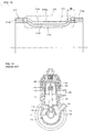
- Fig. 14 is a longitudinal sectional view showing a 2-cycle engine using needle roller bearings at a small end part and a large end part of a connecting rod.
- the 2-cycle engine comprises a crankshaft 103 that outputs a rotary motion, a piston 105 that conducts a linear reciprocating movement by means of combustion of mixture gas, and a connecting rod 104 connecting the crankshaft 103 to the piston 105 to convert the linear reciprocating motion to the rotary motion.
- the crankshaft 103 rotates around a rotation center shaft 111 and a balance weight 112 maintains the rotation balance.
- the connecting rod 104 comprises a large end part 115 at a lower part of a linear rod body and a small end part 116 at an upper part thereof.
- the crankshaft 103 is rotatably supported by the large end part 115 of the connecting rod 104 and a piston pin 114 connecting the piston 105 to the connecting rod 104 is rotatably supported by the small end part 116 of the connecting rod 104 through each roller bearing 106.
- a mixture of gasoline and lubrication oil is sent from an inlet 107 to a crank chamber 102 and then sent to a combustion chamber 109 provided above a cylinder 101 according to a vertical movement of the piston 105 and burned. Exhaust gas after burning is exhausted from an outlet 108.
- a shell type needle roller bearing which can receive high load and has highly rigidity in spite of its small bearing projected area is used as the above roller bearings which are provided at the small end part and the large end part of the connecting rod and support the piston pin and the crankshaft.
- the shell type needle roller bearing comprises a shell type outer ring formed by processing a steel plate in a drawing process and the like, needle rollers, and a retainer arranged along an inner diameter surface of the shell type outer ring. Pockets for holding the needle rollers are provided in the retainer and pillar parts positioned between the adjacent pockets retain intervals of the needle rollers.
- a manufacturing method of the retainer contained in the above shell type needle roller bearing will be briefly described.
- a band steel which is a material of the retainer is punched out to form pocket holes having a size in which the rollers can be held.
- the band steel is pressed so that its sectional configuration may be in the form of a V shape.
- the cut band steel is bent and formed into a cylindrical shape, end surfaces of the bent steel plate are bonded by welding and the like, and a heat treatment process is performed for it, whereby the retainer is manufactured.
- Figs. 15A and 15B are sectional views showing the band steel in the diameter direction before and after the band steel is formed into the cylindrical shape after the pressing and cutting processes, respectively. Since an interval of pillar parts 126 on an inner diameter surface 132 before the retainer is formed into the cylindrical shape (Fig. 15A) becomes small after the retainer is formed into the cylindrical shape (Fig. 15B), a needle roller 123 retained in the pocket can be prevented from falling off toward the inner diameter surface 132. In this case, when a component to prevent the roller from escaping is further provided on the side of an outer diameter surface 131 of the pillar part 126, the needle roller 123 is prevented from escaping toward the outer diameter surface 131.
- Fig. 16 is a view showing a state in which a retainer 124 retaining the needle rollers 123 is incorporated in an outer ring 122 and a shaft 121.
- the needle roller 123 can be guided in the vicinity of a PCD (Pitch Circle Diameter) 125 in which the movement of the needle roller 123 can be most stably controlled.
- the material of the retainer is punched out by a punch having a punching blade such that a pocket configuration is pressed with the blade and punched out.
- a sheared surface and a fractured surface are generated in a sidewall surface of the punched pocket.
- the sheared surface is a flat and smooth surface punched out with the punching blade of the punch and the like, and the fractured surface is a rough surface fractured by a material pressed by the blade.
- the fractured surface is positioned on the side which becomes the outer diameter surface of the sidewall surface of the pillar part.
- Fig. 17 is a sectional view showing the retainer 124 in a diameter direction in the above case
- Fig. 18 is a sectional view of the retainer in an axial direction in the above case.
- a part surrounded by a dotted line is the needle roller 123 held in the pocket of the retainer 124 and a one-dot chain line shows the PCD 125.
- a sheared surface 128 is formed on the side of the inner diameter surface 132 of a sidewall surface 130 and a fractured surface 129 is formed on the side of the outer diameter surface 131 of the sidewall surface 130.
- the retainer 124 is pressed into the V shape in section, when the needle roller 123 is held therein, the fractured surface 129 is positioned in the center part of the sidewall surface 130 in the vicinity of the PCD 125, and the sheared surface 128 is positioned at ends of the sidewall surface 130 in the vicinity of the PCD 125.
- a configuration curve 134 of the sidewall surface 130 along the PCD 125 in this case is shown in Fig. 19 together with an outline 133 of the needle roller 123.
- the center of the sidewall surface 130 is the fractured surface 129 and end parts thereof are the sheared surface 128.
- the configuration curve 134 is recessed to the center part with respect to the outline 133, so that the needle roller 123 is in contact with the sheared surface 128 at the end parts of the sidewall surface 130 when guided.
- the end part of the needle roller 123 is a chamfered part and the end part of the sidewall surface 130 does not have a configuration to follow the outline 133 of the needle roller 123, they cannot be appropriately in contact with each other, so that the needle roller 123 cannot be stably guided.
- the roller bearing comprising such retainer is used in the piston pin supporting structure of the 2-cycle engine and the like, the roller is skewed and seizing could occur.
- a shell type roller bearing for a laminated connecting rod has the similar problems.
- the connecting rod used in the engine is manufactured by forging, sintering or restraint pressure forming a steel rod material or a plate material. As another method, the connecting rod is punched out from a steel plate by a pressing process.
- the connecting rod is manufactured by the forging or sintering process, since many manufacturing steps are required, it is difficult to reduce its cost. Furthermore, when a hole and the like is formed in the connecting rod, since a grinding process and the like is to be performed, the number of steps is further increased.
- connecting rod division parts having a large end part, a small end part and a rod part individually are laminated and the laminated connecting rod division parts are integrally fixed so that the adjacent connecting rod division parts are connected by engaging a connecting projection formed in the rod part by a pressing process with a recess formed on a back surface of the projection or with a through hole formed separately from the projection
- Japanese Unexamined Patent Publication No. 2004-324760 Japanese Unexamined Patent Publication No. 2004-324760 , for example).
- the connecting rod division parts are laminated, even when an inner diameter surface of the large end part or the small end part of the connecting rod division part is skewed, the skew of an inner diameter surface of a large end or a small end of the laminated connecting rod can be eliminated.
- the connecting rod division parts when each of the connecting rod division parts is normally pressed out, the large end part or the small end part of each connecting rod division part is skewed because of its fractured surface.
- each thickness is small because of division, a level difference between a sheared surface and a fractured surface is small, and fractured surfaces are dispersed when laminated.
- the skew of the inner diameter surface of the large end or the small end of the laminated body can be eliminated as a whole.
- the connecting rod assembly can be manufactured easily and inexpensively.
- the laminated connecting rod division parts are connected by engaging the projection pressed in the rod part with the recess formed on the back surface of the projection, or with the through hole formed separately from the projection, they can be rigidly connected. Since the laminated connecting rod division parts are connected by means of the projection and the recess and the like at the rod part, bending strength and buckling strength at the rod part are improved. Since the projection and the recess formed on the back surface thereof are provided by the pressing process, they can be easily formed.
- the shell type roller bearing comprising the shell type outer ring formed by the pressing process including the drawing step, the plurality of needle rollers arranged along the inner diameter surface of the outer ring, and the retainer retaining these needle rollers can be employed.
- the conventional shell type needle roller bearing has problems described with reference to Figs. 15 to 19.
- a needle roller bearing according to the present invention comprises a plurality of needle rollers and a retainer for retaining the needle rollers.
- the above retainer includes a pair of annular parts and pillar parts connecting the pair of annular parts so as to form pockets in which the needle rollers are housed.
- a sidewall surface of the pillar part has a sheared surface punched by a punching blade so that the pockets are formed, and a fractured surface fractured by a material pressed by the punching blade.
- the above needle roller is guided by the sheared surface.
- the roller in the sidewall surface of the pillar part for guiding the roller, the roller can be guided by the flat and smooth sheared surface provided in the center and following the outline of the roller, so that the rollers can be guided stably.
- the pillar part has a configuration in which its center part is recessed toward the inside in a diameter direction, the sheared surface is positioned on the outside in the diameter direction, and the fractured surface is positioned on the inside in the diameter direction.
- the sheared surface can be positioned in the vicinity of the PCD, the rollers can be guided stably.
- a length of the sheared surface in an axial direction that guides the needle roller is not less than 60% of a length of the needle roller in the axial direction.
- a retainer of a needle roller bearing retains a plurality of needle rollers.
- the retainer comprises a pair of annular parts and pillar parts connecting the pair of annular parts so as to form pockets in which the needle rollers are housed.
- the pillar part has a configuration in which its center part is recessed toward the inside in a diameter direction.
- a sidewall surface of the pillar part has a sheared surface punched by a punching blade so that the pocket is formed, and a fractured surface fractured by a material pressed by the punching blade.
- a piston supporting structure of an engine comprises a piston pin for connecting the piston to a small end part of a connecting rod and a bearing for supporting the piston pin.
- the bearing comprises a plurality of rollers and a retainer for retaining the rollers.
- the retainer includes a pair of annular parts and pillar parts connecting the pair of annular parts so as to form pockets in which the needle rollers are housed.
- a sidewall surface of the pillar part has a sheared surface punched by a punching blade so that the pocket is formed, and a fractured surface fractured by a material pressed by the punching blade, and the roller is guided by the sheared surface.
- the roller in the sidewall surface of the pillar part for guiding the roller, the roller can be guided by the flat and smooth sheared surface provided in the center and following the outline of the roller, so that the rollers can be guided stably. Therefore, when the piston pin is supported by such bearing, there can be provided a piston pin supporting structure in which the roller is prevented from being skewed and a seizing resistance property is improved.
- the pillar part has a configuration in which its center part is recessed toward the inside in a diameter direction, and the sheared surface is positioned outside in the diameter direction and the fractured surface is positioned inside in the diameter direction.
- the sheared surface can be positioned in the vicinity of the PCD, the roller bearing provided in the piston pin supporting structure of the engine can guide the rollers stably.
- a crankshaft supporting structure comprises a crankshaft connected to a connecting rod for converting a linear reciprocating movement to a rotary motion and outputting a rotary movement and a bearing for supporting the crankshaft.
- the bearing comprises a plurality of rollers and a retainer for retaining the rollers.
- the retainer includes a pair of annular parts and pillar parts connecting the pair of annular parts so as to form pockets in which the needle rollers are housed.
- a sidewall surface of the pillar part has a sheared surface punched by a punching blade so that the pocket is formed, and a fractured surface fractured by a material pressed by the punching blade, and the roller is guided by the sheared surface.
- the roller in the sidewall surface of the pillar part for guiding the roller, the roller can be guided by the flat and smooth sheared surface provided in the center and following the outline of the roller, so that the rollers can be guided stably. Therefore, when the crankshaft is supported by such bearing, there can be provided a crankshaft supporting structure in which the roller is prevented from being skewed and a seizing resistance property is improved.
- the pillar part has a configuration in which its center part is recessed toward the inside in a diameter direction, and the sheared surface is positioned outside in the diameter direction and the fractured surface is positioned inside in the diameter direction.
- the sheared surface can be positioned in the vicinity of the PCD, the roller bearing provided in the crankshaft supporting structure of the engine can guide the rollers stably.
- a 2-cycle engine comprises the above piston pin supporting structure or crankshaft supporting structure.
- a connecting rod assembly comprises a laminated connecting rod and a shell type roller bearing.
- the laminated connecting rod is laminated with plate-shaped connecting rod division parts having a large end part, a small end part and a rod part individually and connected to the adjacent connecting rod division part by engaging a connecting projection formed in the rod part by a pressing process with a recess formed on a back surface of the projection or with a through hole formed separately from the projection.
- the roller bearing has an outer ring, a plurality of needle rollers and a retainer for retaining the plurality of needle rollers. The outer ring of the bearing is press fitted in a bearing engagement hole in a large end or a small end of the laminated connecting rod.
- the retainer has a sectional configuration in which its center part in a width direction is recessed toward an inner diameter with respect to its both ends by the pressing process, and comprises a plurality of pockets provided in a circumferential direction, and pillar parts positioned between the adjacent pockets.
- a sheared surface is generated in the vicinity of the center of the pillar part in the longitudinal direction and a fractured surface is generated at root parts thereof.
- the sheared surface is generated in the vicinity of the center of the pillar part in the longitudinal direction and the fractured surface is formed at root parts thereof in the longitudinal direction. Therefore, for example, when it is incorporated in the connecting rod assembly of the 2 cycle engine and operated, the needle roller and the retainer are in contact with each other on a flat surface in the vicinity of the center of the pillar part in the longitudinal direction. Thus, the needle roller is prevented from being skewed and transversely running in a thrust direction. Thus, a width surface of the shell type outer ring is prevented from coming in contact with an opponent part of the engine, so that seizing of the bearing can be prevented.
- a length of the sheared surface in the vicinity of the center part of the pillar part in the longitudinal direction may be 60% or more of a length of the needle roller.
- the sheared surface in the vicinity of the center part of the pillar part of the retainer in the longitudinal direction becomes short and the length of the contact part between the needle roller and the sheared surface of the retainer becomes short, the movement of the needle roller cannot be sufficiently controlled.
- the length of the sheared surface in the vicinity of the center of the pillar part in the longitudinal direction is provided so as to be not less than 60% of the length of the needle roller, the contact part between the needle roller and the flat sheared surface is long, so that the movement of the needle roller can be stabled.
- the laminated connecting rod division parts are connected by engaging the projection pressed in the rod part with the recess formed on the back surface of the projection, or with the through hole formed separately from the projection, they can be rigidly connected. Since the laminated connecting rod division parts are connected by the projection and the recess and the like, bending strength and buckling strength at the rod part are improved. Since the projection and the recess formed on the back surface thereof are provided by the pressing process, they can be easily formed.
- a manufacturing method of a retainer of a needle roller bearing according to the present invention is a manufacturing method of a retainer of a needle roller bearing having a pair of annular parts and pillar parts connecting the pair of annular parts so as to form pockets in which needle rollers are housed.
- the manufacturing method comprises a punching step of punching out the pocket in such a manner that a side that becomes an outer diameter surface when a cylindrical surface is formed is a sheared surface punched out by a punching blade and a side that becomes an inner diameter surface is a fractured surface fractured by a material pressed by the punching blade in a sidewall of the pillar part, and a pressing step of pressing a center part of the pillar part toward a side that becomes an inner diameter side when the cylindrical surface is formed.
- the roller can be guided on the sheared surface that is smooth and follows the outline of the roller in the center of the sidewall surface of the pillar part in the vicinity of the PCD, the roller can be guided stably.
- the pressing step in the manufacturing method is performed in such a manner that a length of the sheared surface for guiding the needle roller in an axial direction becomes not less than 60% of a length of the needle roller in the axial direction.
- the sheared surface that guides the roller is large, so that the movement of the roller can be controlled further stably.
- needle rollers are set in pockets of the retainer of the needle roller bearing manufactured by any of the above-described methods for manufacturing the retainer of the needle roller bearing.
- the roller When the needle roller bearing is manufactured by such manufacturing method, the roller can be stably guided and a seizing resistance property can be improved.
- Fig. 1 is a sectional view showing an essential part of a 2-cycle engine according to one embodiment of the present invention.
- a 2-cycle engine 10 comprises a piston (not shown) conducting a linear reciprocating movement by means of combustion of mixture gas, a crankshaft 18 outputting a rotary motion, and a connecting rod 15 connecting the piston to the crankshaft 18 to convert the linear reciprocating motion to the rotary motion.
- the piston is connected to a small end part of the connecting rod 15 through a needle roller bearing 11 having a shell type outer ring by a piston pin 17.
- the crankshaft 18 is connected to a large end part of the connecting rod 15 through a needle roller bearing 16 having a shell type outer ring.
- the needle roller bearing 11 in which a peripheral surface of the piston pin 17 is fitted is set in an engagement hole provided at the small end part of the connecting rod 15, whereby a piston pin supporting structure is formed.
- the needle roller bearing 16 in which a peripheral surface of the crankshaft 18 is fitted is set in an engagement hole provided at the large end part of the connecting rod 15, whereby a crankshaft supporting structure is formed.
- the needle roller bearings 11 and 16 mounted on the small end part and the large end part of the connecting rod 15, respectively are different in size, since they have the same constitution, a description will be made of the needle roller bearing 11 hereinafter.
- the needle roller bearing 11 comprises an outer ring 12, a plurality of needle rollers 13 arranged along an inner diameter surface of the outer ring 12, and a retainer 14 for retaining the needle rollers 13.
- the retainer 14 has a pair of annular parts positioned on both ends of the outer ring 12 and pillar parts for connecting the pair of annular parts so as to form pockets in which the needle rollers are housed.
- Fig. 2 is a flowchart showing steps of manufacturing the retainer 14 of the needle roller bearing 11 according to one embodiment of the present invention.
- Fig. 3 is a schematic view showing representative steps among the steps shown in Fig. 2. The manufacturing method of the retainer 14 will be described with reference to Figs. 2 and 3.
- a steel plate that is a material of the retainer 14 in a state of a band steel (Fig. 3A) is punched to form pockets for retaining the needle rollers (Fig. 3B).
- This punching step is performed using a punch having a punching blade so as to press a configuration of the pocket in the band steel with a blade edge and punch it out.
- the punching is performed from a side which become an outer diameter surface when the steel plate is formed into a cylindrical shape at a bending step as will be described below.
- a sidewall surface of the pillar part on the side of the outer diameter surface is a sheared surface and the sidewall surface of the pillar part on the side of the inner diameter surface is a fractured surface.
- the band steel in which pockets are formed is pressed such that its sectional configuration may become a V shape at a pressing step (Fig. 3).
- the V shape means that when the center part and the annular part of the band steel having punched pockets are formed into the cylindrical shape, a stepped part is formed in a diameter direction. This step is performed by pressing the band steel with a press from the side that becomes the outer diameter surface, toward the side that becomes the inner diameter surface later.
- the center of the pillar part is recessed inside in the diameter direction with respect to the annular part.
- a cutting step of cutting the band steel is performed such that a length thereof may be equal to a circumferential length of the retainer 14.
- a bending step is performed such that the cut band steel is formed into the cylindrical shape so as to be along the inner diameter surface of the outer ring 12 (Fig. 3D) and a bonding step of bonding both end surfaces thereof is performed by welding and the like (Fig. 3E).
- a heat treatment step such as a soft nitriding process or a carburized quenching process is performed and the retainer 14 is finally manufactured.
- the plurality of needle rollers 13 are set in the pockets of the retainer 14 manufactured as described above and the retainer 14 retaining the needle rollers 13 is mounted on the outer ring 12, whereby the needle roller bearing 11 is manufactured.
- Fig. 4 is a sectional view showing the retainer 14 manufactured by the above manufacturing steps in an axial direction.
- a dotted line designates the needle roller 13 held in the pocket of the retainer 14 and a one-dot chain line designates a PCD 26.
- a configuration curve 32 of the sidewall surface 25 in the PCD 26 in this case and an outline 31 of the needle roller 13 are shown together in Fig. 5.
- a pillar part 22 is pressed so that its sectional configuration becomes V shape toward an inner diameter surface 28 in the above pressing step. Therefore, the center of the pillar part 22 is positioned on the side of the inner diameter surface 28 with respect to the annular part 21.
- a sheared surface 23 is formed on the side of the outer diameter surface and a fractured surface 24 is formed on the side of the inner diameter surface in the sidewall surface 25 of the pillar part 22. Therefore, along the PCD 26, the sheared surface 23 on the side of the outer diameter surface 27 is positioned in the center of the sidewall surface 25, and the fractured surface 24 on the side of the inner diameter surface 28 is positioned at the ends of the sidewall surface 25.
- the configuration curve 32 of the sheared surface 23 positioned in the center of the sidewall surface 25 is smooth and follows the outline 31 of the needle roller 13.
- a length of the sheared surface in the axial direction that guides the needle roller 13 is not less than 60% of a length of the needle roller 13 in the axial direction.
- the band steel may be pressed such that the length of the sheared surface 23 along the PCD 26 become not less than 60% of the roller length at the above pressing step. More specifically, the band steel is pressed and formed into the V shape in the diameter direction such that a dimension of A in Fig.
- a dimension of the fractured surface on the side of one annular part 21 along the PCD 26 may become not more than 20% of a dimension of B which is a length of the pocket in the axial direction.
- the configuration which is flat and smooth and follows the outline 31 positioned in the center of the configuration curve 32 is not less than 60% of the roller length.
- the roller movement can be controlled and the needle roller 13 can be guided more stably.
- a test for confirming a seizing resistance property was performed for the needle roller bearing having the retainer in which the length of the sheared surface is not less than 60% of the roller length as shown in Fig. 5 as one embodiment, a needle roller bearing having a retainer whose configuration curve 33 is as shown in Fig. 6 and sheared surface is 50% of a roller length as a sample A, and a needle roller bearing having the conventional retainer as a conventional bearing used in connecting rods.
- Table 1 shows the result of the above test. Referring to Table 1, among the conventional needle roller bearings, eight needle roller bearings were seized out of ten. According to the sample A, six needle roller bearings were seized out of ten. According to the inventive example, no needle roller bearing was seized out of ten.
- a piston pin supporting structure of a 2-cycle engine in which a roller is prevented from being skewed and a seizing resistance property is improved.
- the needle roller baring having the above constitution is used in the crankshaft supporting structure of the 2-cycle engine, there can be provided a crankshaft supporting structure of a 2-cycle engine in which a roller is prevented from being skewed and a seizing resistance property is improved.
- a 2-cycle engine in which a roller is prevented from being skewed and a seizing resistance property is improved.
- the shell type needle roller bearing has been described in the above embodiment, a solid type needle roller bearing may be used. Still furthermore, although the needle roller bearing has been described in the above embodiment, a rod roller bearing, a cylindrical roller bearing and the like may be used.
- Figs. 7 to 13 show another embodiment of the present invention.
- Figs. 7A and 7B are a sectional view and a front view showing a connecting rod assembly comprising a shell type roller bearing for a laminated connecting rod, respectively according to this embodiment.
- the connecting rod assembly is used in the 2-cycle engine and especially in a small-size engine, and comprises a laminated connecting rod 201 and shell type roller bearings 204 fitted in a large end 202 and a small end 203 of the laminated connecting rod 201.
- a plurality of (four, here) connecting rod division parts 201A to 201D each having a large end part 201a, a small end part 201b and a rod part 201c are laminated to be integrated.
- the connecting rod division parts 201A to 201D are connected by engaging a projection 205 with a recess 205a formed on the same plane by a pressing process, or engaging the projection 205 with a through hole 206, and press fitting the engagement. That is, when the projection 205 and the recess 205a or the through hole 206 are engaged and press fitted, the connecting rod division parts 201A to 201D are connected to each other.
- the recess 205a is formed on a back side of the projection 205, and the recesses 205a in the back surfaces of the projections 205 of the laminated middle connecting rod division parts 201B and 201C engage with the projections 205 of the connecting rod division parts 201A and 201B, respectively.
- the through hole 206 is formed in the connecting rod division part 201D which is the most outer part with respect to a projecting direction of the projection 205. Although it is enough that the projections 205 or the through hole 206 is provided at one position in the rod part 201c, they are provided at three positions apart from each other in the longitudinal direction of the rod according to this embodiment.
- Each of the connecting rod division parts 201A to 201D is a flat plate component having the same peripheral configuration, in which bearing engagement holes 207 and 208 are formed at its large end part 201a and small end part 201b, respectively.
- the above-described shell type roller bearing 204 is fitted in each of the bearing engagement holes 207 and 208 in a press fitted state.
- the shell type roller bearings 204 fitted in the large end 202 and the small end 203 of the laminated connecting rod 201 are different in size but they are the same in construction.
- the shell type roller bearing 204 comprises a cylindrical shell type outer ring 211 formed by a pressing process including a drawing step, a plurality of needle rollers 212 arranged along an inner diameter surface 211c of the shell type outer ring 211, and a retainer 213 for retaining these needle rollers 212 rotatably as shown in an enlarged sectional view in Fig. 8.
- the shell type outer ring 211 has flanges 211a and 211b bent toward an inner diameter side at both ends.
- the retainer 213 is cylindrically formed and a plurality of pockets 214 for housing the needle rollers 212 are provided in a circumferential direction of the retainer 213.
- the retainer 213 comprises ring-shaped parts 213a on both ends and pillar parts 213b formed between the pockets 214 adjacent to each other in the circumferential direction and connected to the ring-shaped parts 213a on both sides.
- the ring-shaped parts 213a on both sides of the retainer 213 are oppositely disposed on the inner diameter side of the flanges 211a and 211b of the shell type outer ring 211.
- the retainer 213 is formed of a steel material and manufactured by a pressing process.
- the retainer 213 is manufactured by steps shown in a flowchart schematically shown in Fig. 9 as follows. First, the pockets 214 are punched out from a band steel 220 at a pocket punching-out step using a punch. At the next step, a pillar part 213b (in Fig. 8) sandwiched between the adjacent pockets 214 is pressed so that its center part in the longitudinal direction (a middle part of the retainer 213 in a width direction) is recessed in sectional configuration with respect to its both ends. At this time, the pressing is performed from the surface from which the punch was inserted at the pocket punching-out step. Then, the pressed half-finished product is cut to a predetermined length at the next step. At the next step, the cut half-finished product in the form of a band is formed into a cylindrical shape.
- the half-finished product is bent and formed into the cylindrical shape such that a recessed part 213ba of the middle part of the pillar part 213b in the longitudinal direction is provided on an inner diameter side, that is, such that the side from which the punch was inserted at the pocket punching-out step as shown in Fig. 11 becomes its outer circumference.
- the sheared surface is generated on the punch-inserted side and the fractured surface is generated on the opposite side of the punch-inserted side in an inner surface of the pocket 214.
- a sheared surface 214a is generated on the side of the outer circumference and a fractured surface 214b is generated on the side of the inner circumference in the inner surface of the pocket 214 in the form of the cylindrical shape as shown in Fig. 11.
- both ends of the half-finished cylindrical product in a circumferential direction are bonded to form a ring by welding.
- soft nitriding or carburized quenching is performed for the ring-shaped retainer 213 at a heat treatment step.
- Fig. 12 is a sectional view showing a state in which a shaft 210 is inserted into the shell type roller bearing 204 and Fig. 13 is a partially enlarged sectional view showing the pocket 214 in the retainer 13, which is cut in the width direction of the retainer.
- the needle roller 212 is shown by a two-dot chain line.
- a part of the PCD (Fig. 12) along which the needle rollers 212 are arranged in the longitudinal direction of the inner surface of the pocket 214 is shown by a line 215 in Fig 13.
- a line 215 in a part of the PCD (Fig. 12) along which the needle rollers 212 are arranged in the longitudinal direction of the inner surface of the pocket 214 is shown by a line 215 in Fig 13.
- a part on the outer circumference side shown by an outline part is the sheared surface 214a and a part on the inner circumference side shown by dashed lines is the fractured surface 214b. That is, in the line (215) of the PCD along which the needle rollers 212 are arranged in the longitudinal direction of the inner surface of the pocket 214, the sheared surface 214a is formed in the vicinity of the center of the pillar part 213b in the longitudinal direction and the fractured surface 214b is formed at roots, that is, on both ends thereof in the longitudinal direction.
- a length of the sheared surface 214a in the longitudinal direction in the vicinity of the center of the pillar part 213b, that is, the recessed part 213ba is set so as to be not less than 60% of a length of the needle roller 212.
- a length of the sheared surface 214a in a diameter direction is adjusted so that a length W from an end of the pocket to an intersection point between the sheared surface 214a and the line 215 on the PCD may be not more than 20% of the roller length.
- the sheared surface 214a is generated in the vicinity of the center of the pillar part 213b in the longitudinal direction and the fractured surface 214b is formed at the root parts, that is, at both ends thereof in the longitudinal direction. Therefore, since the needle roller 212 and the retainer 213 are in contact with each other in the vicinity of the center of the pillar part 213b in the longitudinal direction during operation, the needle roller 212 does not in contact with the fractured surface 214b at the roots of the pillar part 213b, in which fracture was generated at the pocket-punching step.
- the needle roller 212 can come in contact with the retainer 213 stably, the needle roller 212 is prevented from being skewed and transversely running in a thrust direction.
- a width surface of the shell type outer ring 211 is prevented from coming in contact with an opponent part of the engine, so that seizing of the bearing can be prevented.
- the sheared surface 214a in the vicinity of the center of the pillar part 213b of the retainer in the longitudinal direction becomes short and the length of the contact part between the needle roller 212 and the sheared surface 214a of the retainer 213 having the above constitution becomes short, the movement of the needle roller 212 cannot be sufficiently controlled.
- the length of the sheared surface 214a in the vicinity of the center of the pillar part 213b in the longitudinal direction that is, the length of the recessed part 213ba is provided so as to be not less than 60% of the length of the needle roller 212, the contact part between the needle roller 212 and the sheared surface 214a is long, so that the movement of the needle roller 212 can be stabled.
- the shell roller bearing 204 having the above constitution is press fitted in the bearing engagement hole 207 or 208 in the large end 202 or the small end 203 (both large end 202 and small end 203 in the embodiment) in the laminated connecting rod 201 to constitute the connecting rod assembly, other than the above effect provided by the shell type roller bearing 204, there is provided the following effect.
- the laminated connecting rod division parts 201A to 201D are connected by engaging the connecting projection 205 formed by pressing the rod part 201c with the recess 205a formed on the back surface of the projection 205, or with the through hole 206 formed separately from the projection 205, they can be rigidly connected. Since the laminated connecting rod division parts 201A to 201D are connected by means of the projection 205 and the recess 205a and the like at the rod part 201c, bending strength and buckling strength at the rod part 201 are improved. Since the projection 205 and the recess 205a formed on the back surface thereof are provided by the pressing process, they can be easily formed.
Abstract
Description
- The present invention relates to a needle roller bearing, a retainer of the needle roller bearing and their manufacturing methods. Furthermore, the present invention relates to various kinds of structures comprising the needle roller bearing.
- A 2-cycle engine having a small engine capacity is used in a utility engine in an agricultural machine and the like. A technique regarding such 2-cycle engine is disclosed in
Japanese Unexamined Patent Publication No. 7-332371 - Fig. 14 is a longitudinal sectional view showing a 2-cycle engine using needle roller bearings at a small end part and a large end part of a connecting rod. Referring to Fig. 14, the 2-cycle engine comprises a
crankshaft 103 that outputs a rotary motion, apiston 105 that conducts a linear reciprocating movement by means of combustion of mixture gas, and a connectingrod 104 connecting thecrankshaft 103 to thepiston 105 to convert the linear reciprocating motion to the rotary motion. Thecrankshaft 103 rotates around arotation center shaft 111 and abalance weight 112 maintains the rotation balance. - The connecting
rod 104 comprises alarge end part 115 at a lower part of a linear rod body and asmall end part 116 at an upper part thereof. Thecrankshaft 103 is rotatably supported by thelarge end part 115 of the connectingrod 104 and apiston pin 114 connecting thepiston 105 to the connectingrod 104 is rotatably supported by thesmall end part 116 of the connectingrod 104 through each roller bearing 106. - A mixture of gasoline and lubrication oil is sent from an
inlet 107 to acrank chamber 102 and then sent to acombustion chamber 109 provided above acylinder 101 according to a vertical movement of thepiston 105 and burned. Exhaust gas after burning is exhausted from anoutlet 108. - A shell type needle roller bearing which can receive high load and has highly rigidity in spite of its small bearing projected area is used as the above roller bearings which are provided at the small end part and the large end part of the connecting rod and support the piston pin and the crankshaft. Here, the shell type needle roller bearing comprises a shell type outer ring formed by processing a steel plate in a drawing process and the like, needle rollers, and a retainer arranged along an inner diameter surface of the shell type outer ring. Pockets for holding the needle rollers are provided in the retainer and pillar parts positioned between the adjacent pockets retain intervals of the needle rollers.
- Here, a manufacturing method of the retainer contained in the above shell type needle roller bearing will be briefly described. First, a band steel which is a material of the retainer is punched out to form pocket holes having a size in which the rollers can be held. Then, the band steel is pressed so that its sectional configuration may be in the form of a V shape. After the pressing process, it is cut to a length that is equal to a circumferential length of the retainer, the cut band steel is bent and formed into a cylindrical shape, end surfaces of the bent steel plate are bonded by welding and the like, and a heat treatment process is performed for it, whereby the retainer is manufactured.
- Here, when the band steel is pressed to be formed into the V shape in section, since a sectional height in a diameter direction can be ensured, the following effect is provided. Figs. 15A and 15B are sectional views showing the band steel in the diameter direction before and after the band steel is formed into the cylindrical shape after the pressing and cutting processes, respectively. Since an interval of
pillar parts 126 on aninner diameter surface 132 before the retainer is formed into the cylindrical shape (Fig. 15A) becomes small after the retainer is formed into the cylindrical shape (Fig. 15B), aneedle roller 123 retained in the pocket can be prevented from falling off toward theinner diameter surface 132. In this case, when a component to prevent the roller from escaping is further provided on the side of anouter diameter surface 131 of thepillar part 126, theneedle roller 123 is prevented from escaping toward theouter diameter surface 131. - In addition, Fig. 16 is a view showing a state in which a
retainer 124 retaining theneedle rollers 123 is incorporated in anouter ring 122 and ashaft 121. By the pressing process performed to form the sectional configuration into the V shape, theneedle roller 123 can be guided in the vicinity of a PCD (Pitch Circle Diameter) 125 in which the movement of theneedle roller 123 can be most stably controlled. - In addition, a retainer of a needle roller bearing having the same configuration as that of the retainer manufactured by the above steps is disclosed in
Japanese Unexamined Patent Publication 2005-98368 - In the above pocket punching-out process, the material of the retainer is punched out by a punch having a punching blade such that a pocket configuration is pressed with the blade and punched out. At this time, in a sidewall surface of the punched pocket, that is, a sidewall surface of the pillar part positioned between the pockets, a sheared surface and a fractured surface are generated. The sheared surface is a flat and smooth surface punched out with the punching blade of the punch and the like, and the fractured surface is a rough surface fractured by a material pressed by the blade.
- Here, in the pocket punching-out process, when the pocket is punched out from the side which becomes an inner diameter surface when the material is formed into the cylindrical shape, the fractured surface is positioned on the side which becomes the outer diameter surface of the sidewall surface of the pillar part.
- Fig. 17 is a sectional view showing the
retainer 124 in a diameter direction in the above case, and Fig. 18 is a sectional view of the retainer in an axial direction in the above case. In Fig. 18, a part surrounded by a dotted line is theneedle roller 123 held in the pocket of theretainer 124 and a one-dot chain line shows the PCD 125. Referring to Figs. 17 and 18, when the pocket is punched out from a direction of an arrow X in the drawings, which is the side of theinner diameter surface 132, asheared surface 128 is formed on the side of theinner diameter surface 132 of asidewall surface 130 and a fracturedsurface 129 is formed on the side of theouter diameter surface 131 of thesidewall surface 130. Here, since theretainer 124 is pressed into the V shape in section, when theneedle roller 123 is held therein, the fracturedsurface 129 is positioned in the center part of thesidewall surface 130 in the vicinity of thePCD 125, and thesheared surface 128 is positioned at ends of thesidewall surface 130 in the vicinity of thePCD 125. - A
configuration curve 134 of thesidewall surface 130 along the PCD 125 in this case is shown in Fig. 19 together with anoutline 133 of theneedle roller 123. Referring to Fig. 19, the center of thesidewall surface 130 is the fracturedsurface 129 and end parts thereof are thesheared surface 128. Thus, theconfiguration curve 134 is recessed to the center part with respect to theoutline 133, so that theneedle roller 123 is in contact with thesheared surface 128 at the end parts of thesidewall surface 130 when guided. - However, since the end part of the
needle roller 123 is a chamfered part and the end part of thesidewall surface 130 does not have a configuration to follow theoutline 133 of theneedle roller 123, they cannot be appropriately in contact with each other, so that theneedle roller 123 cannot be stably guided. When the roller bearing comprising such retainer is used in the piston pin supporting structure of the 2-cycle engine and the like, the roller is skewed and seizing could occur. - A shell type roller bearing for a laminated connecting rod has the similar problems.
- The connecting rod used in the engine is manufactured by forging, sintering or restraint pressure forming a steel rod material or a plate material. As another method, the connecting rod is punched out from a steel plate by a pressing process. When the connecting rod is manufactured by the forging or sintering process, since many manufacturing steps are required, it is difficult to reduce its cost. Furthermore, when a hole and the like is formed in the connecting rod, since a grinding process and the like is to be performed, the number of steps is further increased.
- As a connecting rod assembly which can be easily and inexpensively manufactured, prevent a bearing and the like to be set in a large end part or a small end part from being skewed, and improve bending strength and buckling strength, there is proposed an assembly in which connecting rod division parts having a large end part, a small end part and a rod part individually are laminated and the laminated connecting rod division parts are integrally fixed so that the adjacent connecting rod division parts are connected by engaging a connecting projection formed in the rod part by a pressing process with a recess formed on a back surface of the projection or with a through hole formed separately from the projection (
Japanese Unexamined Patent Publication No. 2004-324760 - According to this construction, since the connecting rod division parts are laminated, even when an inner diameter surface of the large end part or the small end part of the connecting rod division part is skewed, the skew of an inner diameter surface of a large end or a small end of the laminated connecting rod can be eliminated. For example, when each of the connecting rod division parts is normally pressed out, the large end part or the small end part of each connecting rod division part is skewed because of its fractured surface. However, since each thickness is small because of division, a level difference between a sheared surface and a fractured surface is small, and fractured surfaces are dispersed when laminated. Thus, the skew of the inner diameter surface of the large end or the small end of the laminated body can be eliminated as a whole. Therefore, when the shell type roller bearings are press fitted in the large end and the small end, the outer ring is not skewed. Thus, since each of the connecting rod division parts can be pressed out, it is not necessary to perform a post-process such as grinding or polishing for the large end part and the small end part. Thus, the connecting rod assembly can be manufactured easily and inexpensively.
- Furthermore, since the laminated connecting rod division parts are connected by engaging the projection pressed in the rod part with the recess formed on the back surface of the projection, or with the through hole formed separately from the projection, they can be rigidly connected. Since the laminated connecting rod division parts are connected by means of the projection and the recess and the like at the rod part, bending strength and buckling strength at the rod part are improved. Since the projection and the recess formed on the back surface thereof are provided by the pressing process, they can be easily formed.
- As a bearing in this connecting rod assembly, the shell type roller bearing comprising the shell type outer ring formed by the pressing process including the drawing step, the plurality of needle rollers arranged along the inner diameter surface of the outer ring, and the retainer retaining these needle rollers can be employed. The conventional shell type needle roller bearing has problems described with reference to Figs. 15 to 19.
- It is an object of the present invention to provide a needle roller bearing that can guide rollers stably.
- It is another object of the present invention to provide a piston supporting structure of an engine comprising the above needle roller bearing.
- It is still another object of the present invention to provide a crankshaft supporting structure of an engine comprising the above needle roller bearing.
- It is still another object of the present invention to provide a shell type roller bearing for a laminated connecting rod and a connecting rod assembly that can prevent a roller from being skewed and running transversely using a press retainer having a simple constitution.
- It is still another object of the present invention to provide a retainer of the needle roller bearing that can guide rollers stably.
- It is still another object of the present invention to provide a manufacturing method of the retainer of the needle roller bearing that can guide rollers stably.
- A needle roller bearing according to the present invention comprises a plurality of needle rollers and a retainer for retaining the needle rollers. The above retainer includes a pair of annular parts and pillar parts connecting the pair of annular parts so as to form pockets in which the needle rollers are housed. Here, a sidewall surface of the pillar part has a sheared surface punched by a punching blade so that the pockets are formed, and a fractured surface fractured by a material pressed by the punching blade. The above needle roller is guided by the sheared surface.
- According to the above constitution, in the sidewall surface of the pillar part for guiding the roller, the roller can be guided by the flat and smooth sheared surface provided in the center and following the outline of the roller, so that the rollers can be guided stably.
- Preferably, the pillar part has a configuration in which its center part is recessed toward the inside in a diameter direction, the sheared surface is positioned on the outside in the diameter direction, and the fractured surface is positioned on the inside in the diameter direction. Thus, since the sheared surface can be positioned in the vicinity of the PCD, the rollers can be guided stably.
- Further preferably, a length of the sheared surface in an axial direction that guides the needle roller is not less than 60% of a length of the needle roller in the axial direction. Thus, since the large sheared surface can guide the roller, the movement of the roller can be stabled.
- According to another aspect of the present invention, a retainer of a needle roller bearing retains a plurality of needle rollers. The retainer comprises a pair of annular parts and pillar parts connecting the pair of annular parts so as to form pockets in which the needle rollers are housed. The pillar part has a configuration in which its center part is recessed toward the inside in a diameter direction. Here, a sidewall surface of the pillar part has a sheared surface punched by a punching blade so that the pocket is formed, and a fractured surface fractured by a material pressed by the punching blade.
- When this retainer of the needle roller bearing is used, there is provided a needle roller bearing that can guide the rollers stably.
- A piston supporting structure of an engine according to the present invention comprises a piston pin for connecting the piston to a small end part of a connecting rod and a bearing for supporting the piston pin. The bearing comprises a plurality of rollers and a retainer for retaining the rollers. The retainer includes a pair of annular parts and pillar parts connecting the pair of annular parts so as to form pockets in which the needle rollers are housed. Here, a sidewall surface of the pillar part has a sheared surface punched by a punching blade so that the pocket is formed, and a fractured surface fractured by a material pressed by the punching blade, and the roller is guided by the sheared surface.
- According to the above constitution, in the sidewall surface of the pillar part for guiding the roller, the roller can be guided by the flat and smooth sheared surface provided in the center and following the outline of the roller, so that the rollers can be guided stably. Therefore, when the piston pin is supported by such bearing, there can be provided a piston pin supporting structure in which the roller is prevented from being skewed and a seizing resistance property is improved.
- Preferably, the pillar part has a configuration in which its center part is recessed toward the inside in a diameter direction, and the sheared surface is positioned outside in the diameter direction and the fractured surface is positioned inside in the diameter direction. Thus, since the sheared surface can be positioned in the vicinity of the PCD, the roller bearing provided in the piston pin supporting structure of the engine can guide the rollers stably.
- According to still another aspect of the present invention, a crankshaft supporting structure comprises a crankshaft connected to a connecting rod for converting a linear reciprocating movement to a rotary motion and outputting a rotary movement and a bearing for supporting the crankshaft. The bearing comprises a plurality of rollers and a retainer for retaining the rollers. The retainer includes a pair of annular parts and pillar parts connecting the pair of annular parts so as to form pockets in which the needle rollers are housed. Here, a sidewall surface of the pillar part has a sheared surface punched by a punching blade so that the pocket is formed, and a fractured surface fractured by a material pressed by the punching blade, and the roller is guided by the sheared surface.
- According to the above constitution, in the sidewall surface of the pillar part for guiding the roller, the roller can be guided by the flat and smooth sheared surface provided in the center and following the outline of the roller, so that the rollers can be guided stably. Therefore, when the crankshaft is supported by such bearing, there can be provided a crankshaft supporting structure in which the roller is prevented from being skewed and a seizing resistance property is improved.
- Preferably, the pillar part has a configuration in which its center part is recessed toward the inside in a diameter direction, and the sheared surface is positioned outside in the diameter direction and the fractured surface is positioned inside in the diameter direction. Thus, since the sheared surface can be positioned in the vicinity of the PCD, the roller bearing provided in the crankshaft supporting structure of the engine can guide the rollers stably.
- According to still another aspect of the present invention, a 2-cycle engine comprises the above piston pin supporting structure or crankshaft supporting structure.
- According to the above constitution, there can be provided a 2-cycle engine in which the roller is prevented from being skewed and a seizing resistance property is improved.
- A connecting rod assembly according to the present invention comprises a laminated connecting rod and a shell type roller bearing. The laminated connecting rod is laminated with plate-shaped connecting rod division parts having a large end part, a small end part and a rod part individually and connected to the adjacent connecting rod division part by engaging a connecting projection formed in the rod part by a pressing process with a recess formed on a back surface of the projection or with a through hole formed separately from the projection. The roller bearing has an outer ring, a plurality of needle rollers and a retainer for retaining the plurality of needle rollers. The outer ring of the bearing is press fitted in a bearing engagement hole in a large end or a small end of the laminated connecting rod. The retainer has a sectional configuration in which its center part in a width direction is recessed toward an inner diameter with respect to its both ends by the pressing process, and comprises a plurality of pockets provided in a circumferential direction, and pillar parts positioned between the adjacent pockets. In a part positioned on a pitch circle diameter along which the needle roller is arranged in an inner surface of the pocket in a longitudinal direction, a sheared surface is generated in the vicinity of the center of the pillar part in the longitudinal direction and a fractured surface is generated at root parts thereof.
- According to this constitution, in the part of the pitch circle diameter along which the needle roller of the retainer is arranged, the sheared surface is generated in the vicinity of the center of the pillar part in the longitudinal direction and the fractured surface is formed at root parts thereof in the longitudinal direction. Therefore, for example, when it is incorporated in the connecting rod assembly of the 2 cycle engine and operated, the needle roller and the retainer are in contact with each other on a flat surface in the vicinity of the center of the pillar part in the longitudinal direction. Thus, the needle roller is prevented from being skewed and transversely running in a thrust direction. Thus, a width surface of the shell type outer ring is prevented from coming in contact with an opponent part of the engine, so that seizing of the bearing can be prevented.
- According to the present invention, a length of the sheared surface in the vicinity of the center part of the pillar part in the longitudinal direction may be 60% or more of a length of the needle roller. When the sheared surface in the vicinity of the center part of the pillar part of the retainer in the longitudinal direction becomes short and the length of the contact part between the needle roller and the sheared surface of the retainer becomes short, the movement of the needle roller cannot be sufficiently controlled. However, as described above, when the length of the sheared surface in the vicinity of the center of the pillar part in the longitudinal direction is provided so as to be not less than 60% of the length of the needle roller, the contact part between the needle roller and the flat sheared surface is long, so that the movement of the needle roller can be stabled.
- Furthermore, other than the above effect provided by the shell type roller bearing, there is provided the following effect.
- That is, even when an inner diameter surface of the large end part or the small end part of each of the connecting rod division parts is skewed due to a pressing process, skew of an inner diameter surface of a large end or a small end of the laminated connecting rod can be eliminated. Therefore, when the outer ring of the shell type roller bearings are press fitted in the large end and the small end, the outer ring is not skewed. Thus, since a pressed-out product can be used for each of the connecting rod division parts, it is not necessary to perform a post-process such as grinding or polishing for the large end part and the small end part. Furthermore, since the laminated connecting rod division parts are connected by engaging the projection pressed in the rod part with the recess formed on the back surface of the projection, or with the through hole formed separately from the projection, they can be rigidly connected. Since the laminated connecting rod division parts are connected by the projection and the recess and the like, bending strength and buckling strength at the rod part are improved. Since the projection and the recess formed on the back surface thereof are provided by the pressing process, they can be easily formed.
- Thus, with the laminated connecting rod which is an inexpensive punched-out product and the shell type bearing using an inexpensive retainer, when the connecting rod in which the shell type outer ring can be press fitted without being skewed is combined with the bearing which can prevent the roller from being skewed and running transversely, there is provided a connecting rod assembly which is inexpensive as a whole and superior in various kinds of functions.
- A manufacturing method of a retainer of a needle roller bearing according to the present invention is a manufacturing method of a retainer of a needle roller bearing having a pair of annular parts and pillar parts connecting the pair of annular parts so as to form pockets in which needle rollers are housed. The manufacturing method comprises a punching step of punching out the pocket in such a manner that a side that becomes an outer diameter surface when a cylindrical surface is formed is a sheared surface punched out by a punching blade and a side that becomes an inner diameter surface is a fractured surface fractured by a material pressed by the punching blade in a sidewall of the pillar part, and a pressing step of pressing a center part of the pillar part toward a side that becomes an inner diameter side when the cylindrical surface is formed.
- When the retainer of the needle roller bearing is manufactured by the above steps, since the roller can be guided on the sheared surface that is smooth and follows the outline of the roller in the center of the sidewall surface of the pillar part in the vicinity of the PCD, the roller can be guided stably.
- Preferably, the pressing step in the manufacturing method is performed in such a manner that a length of the sheared surface for guiding the needle roller in an axial direction becomes not less than 60% of a length of the needle roller in the axial direction. When the retainer of the needle roller bearing is manufactured by the above step, the sheared surface that guides the roller is large, so that the movement of the roller can be controlled further stably.
- According to manufacturing method of a needle roller bearing in another aspect of the present invention, needle rollers are set in pockets of the retainer of the needle roller bearing manufactured by any of the above-described methods for manufacturing the retainer of the needle roller bearing.
- When the needle roller bearing is manufactured by such manufacturing method, the roller can be stably guided and a seizing resistance property can be improved.
-
- Fig. 1 is a sectional view showing an essential part of a 2-cycle engine according to one embodiment of the present invention;
- Fig. 2 is a flowchart showing manufacturing steps of a retainer of a needle roller bearing;
- Fig. 3A is a perspective view showing a band steel which is a starting material in manufacturing the retainer;
- Fig. 3B is a perspective view showing a state after a step of punching out pockets;
- Fig. 3C is a perspective view showing a state after a pressing step;
- Fig. 3D is a perspective view showing a state after a bending step;
- Fig. 3E is a perspective view showing a state of a final product;
- Fig. 4 is a sectional view showing the retainer of the needle roller bearing in an axial direction;
- Fig. 5 is a view showing a configuration curve of a sidewall surface along the PCD when a sheared surface is 60% or more, together with an outline of a needle roller;
- Fig. 6 is a view showing a configuration curve of a sidewall surface of a sample A along the PCD when a sheared surface is 50%, together with the outline of the needle roller;
- Fig. 7A is a front view showing a connecting rod assembly comprising a shell type roller bearing for a laminated connecting rod according to another embodiment of the present invention;
- Fig. 7B is a sectional view showing the connecting rod assembly shown in Fig. 7A;
- Fig. 8 is an enlarged view showing a shell type roller bearing fitted in the connecting rod assembly;
- Fig. 9 is a flowchart showing manufacturing steps of a retainer of the shell type roller bearing;
- Fig. 10 is an explanatory view for a bending step in the manufacturing steps;
- Fig. 11 is an explanatory view showing a side from which a punch is inserted into the retainer;
- Fig. 12 is a sectional view showing the shell type roller bearing taken along its width direction;
- Fig. 13 is a half-enlarged sectional view showing the retainer taken along its width direction;
- Fig. 14 is a longitudinal sectional view showing a 2-cycle engine in which needle roller bearings are used at a large end part and a small end part of a connecting rod;
- Fig. 15A is a sectional view showing a state before a material of the retainer, a band steel, is formed into a cylindrical shape taken along its diameter direction;
- Fig. 15B is a sectional view showing a state after the band steel is bent and formed into the cylindrical shape taken along its diameter direction;
- Fig. 16 is a view showing a state in which a needle roller is held in a pocket of the retainer that is formed into a V shape in section by a pressing process;
- Fig. 17 is a sectional view showing a state in which a sheared surface is positioned on the side of an inner diameter surface and a fractured surface is positioned on the side of an outer diameter surface in a conventional retainer taken along its diameter direction;
- Fig. 18 is a sectional view showing a state in which a sheared surface is positioned on the side of an inner diameter surface and a fractured surface is positioned on the side of an outer diameter surface in the conventional retainer taken along its axial direction; and
- Fig. 19 is a view showing a configuration curve of a sidewall surface of the conventional retainer along the PCD, together with the outline of the needle roller;
- Embodiments of the present invention will be described with reference to the drawings hereinafter. Fig. 1 is a sectional view showing an essential part of a 2-cycle engine according to one embodiment of the present invention. Referring to Fig. 1, a 2-
cycle engine 10 comprises a piston (not shown) conducting a linear reciprocating movement by means of combustion of mixture gas, acrankshaft 18 outputting a rotary motion, and a connectingrod 15 connecting the piston to thecrankshaft 18 to convert the linear reciprocating motion to the rotary motion. The piston is connected to a small end part of the connectingrod 15 through aneedle roller bearing 11 having a shell type outer ring by apiston pin 17. Thecrankshaft 18 is connected to a large end part of the connectingrod 15 through aneedle roller bearing 16 having a shell type outer ring. - The
needle roller bearing 11 in which a peripheral surface of thepiston pin 17 is fitted is set in an engagement hole provided at the small end part of the connectingrod 15, whereby a piston pin supporting structure is formed. Similarly, theneedle roller bearing 16 in which a peripheral surface of thecrankshaft 18 is fitted is set in an engagement hole provided at the large end part of the connectingrod 15, whereby a crankshaft supporting structure is formed. In addition, although theneedle roller bearings rod 15, respectively are different in size, since they have the same constitution, a description will be made of theneedle roller bearing 11 hereinafter. - The
needle roller bearing 11 comprises anouter ring 12, a plurality ofneedle rollers 13 arranged along an inner diameter surface of theouter ring 12, and aretainer 14 for retaining theneedle rollers 13. Theretainer 14 has a pair of annular parts positioned on both ends of theouter ring 12 and pillar parts for connecting the pair of annular parts so as to form pockets in which the needle rollers are housed. - Here, a description will be made of a manufacturing method of the
retainer 14 among the components constituting theneedle roller bearing 11. - Fig. 2 is a flowchart showing steps of manufacturing the
retainer 14 of theneedle roller bearing 11 according to one embodiment of the present invention. Fig. 3 is a schematic view showing representative steps among the steps shown in Fig. 2. The manufacturing method of theretainer 14 will be described with reference to Figs. 2 and 3. - First, a steel plate that is a material of the
retainer 14 in a state of a band steel (Fig. 3A) is punched to form pockets for retaining the needle rollers (Fig. 3B). This punching step is performed using a punch having a punching blade so as to press a configuration of the pocket in the band steel with a blade edge and punch it out. At this time, the punching is performed from a side which become an outer diameter surface when the steel plate is formed into a cylindrical shape at a bending step as will be described below. - Thus, in the finally manufactured retainer, a sidewall surface of the pillar part on the side of the outer diameter surface is a sheared surface and the sidewall surface of the pillar part on the side of the inner diameter surface is a fractured surface.
- Subsequently, the band steel in which pockets are formed is pressed such that its sectional configuration may become a V shape at a pressing step (Fig. 3). Here, the V shape means that when the center part and the annular part of the band steel having punched pockets are formed into the cylindrical shape, a stepped part is formed in a diameter direction. This step is performed by pressing the band steel with a press from the side that becomes the outer diameter surface, toward the side that becomes the inner diameter surface later. Thus, the center of the pillar part is recessed inside in the diameter direction with respect to the annular part.
- Subsequently, a cutting step of cutting the band steel is performed such that a length thereof may be equal to a circumferential length of the
retainer 14. Then, a bending step is performed such that the cut band steel is formed into the cylindrical shape so as to be along the inner diameter surface of the outer ring 12 (Fig. 3D) and a bonding step of bonding both end surfaces thereof is performed by welding and the like (Fig. 3E). Then, a heat treatment step such as a soft nitriding process or a carburized quenching process is performed and theretainer 14 is finally manufactured. - Then, the plurality of
needle rollers 13 are set in the pockets of theretainer 14 manufactured as described above and theretainer 14 retaining theneedle rollers 13 is mounted on theouter ring 12, whereby theneedle roller bearing 11 is manufactured. - Fig. 4 is a sectional view showing the
retainer 14 manufactured by the above manufacturing steps in an axial direction. Referring to Fig. 4, a dotted line designates theneedle roller 13 held in the pocket of theretainer 14 and a one-dot chain line designates aPCD 26. In addition, aconfiguration curve 32 of thesidewall surface 25 in thePCD 26 in this case and anoutline 31 of theneedle roller 13 are shown together in Fig. 5. - Referring to Figs. 4 ad 5, a
pillar part 22 is pressed so that its sectional configuration becomes V shape toward aninner diameter surface 28 in the above pressing step. Therefore, the center of thepillar part 22 is positioned on the side of theinner diameter surface 28 with respect to theannular part 21. - In addition, since the pocket is punched out with the blade edge of the punch pressed from an
outer diameter surface 27 at the above pocket punching step, a shearedsurface 23 is formed on the side of the outer diameter surface and a fracturedsurface 24 is formed on the side of the inner diameter surface in thesidewall surface 25 of thepillar part 22. Therefore, along thePCD 26, the shearedsurface 23 on the side of theouter diameter surface 27 is positioned in the center of thesidewall surface 25, and the fracturedsurface 24 on the side of theinner diameter surface 28 is positioned at the ends of thesidewall surface 25. - Here, the
configuration curve 32 of the shearedsurface 23 positioned in the center of thesidewall surface 25 is smooth and follows theoutline 31 of theneedle roller 13. Thus, since the center part of theneedle roller 13 and the center part of thesidewall surface 25 can be appropriately in contact with each other, the needle roller can be stably guided. - In addition, it is preferable that a length of the sheared surface in the axial direction that guides the
needle roller 13 is not less than 60% of a length of theneedle roller 13 in the axial direction. Here, in order to implement that the length of the shearedsurface 23 is not less than 60% of the roller length, the band steel may be pressed such that the length of the shearedsurface 23 along thePCD 26 become not less than 60% of the roller length at the above pressing step. More specifically, the band steel is pressed and formed into the V shape in the diameter direction such that a dimension of A in Fig. 4, that is, a dimension of the fractured surface on the side of oneannular part 21 along thePCD 26 may become not more than 20% of a dimension of B which is a length of the pocket in the axial direction. Referring to Fig. 5, the configuration which is flat and smooth and follows theoutline 31 positioned in the center of theconfiguration curve 32 is not less than 60% of the roller length. - Thus, since the sheared
surface 23 which comes in contact with the roller appropriately can be large, the roller movement can be controlled and theneedle roller 13 can be guided more stably. - Here, a test for confirming a seizing resistance property was performed for the needle roller bearing having the retainer in which the length of the sheared surface is not less than 60% of the roller length as shown in Fig. 5 as one embodiment, a needle roller bearing having a retainer whose configuration curve 33 is as shown in Fig. 6 and sheared surface is 50% of a roller length as a sample A, and a needle roller bearing having the conventional retainer as a conventional bearing used in connecting rods.
- Test conditions are as follows. The result of this test is shown in Table 1.
- * Mixture ratio : Gasoline / Lubrication oil = 50 / 1
- * Operation pattern : Full throttle
- * Operation time : Two hours or until seizing is found
- Table 1 shows the result of the above test. Referring to Table 1, among the conventional needle roller bearings, eight needle roller bearings were seized out of ten. According to the sample A, six needle roller bearings were seized out of ten. According to the inventive example, no needle roller bearing was seized out of ten.
- Therefore, when the length of the sheared surface in the axial direction is not less than 60% of the roller length, since there is no seizing generated, it is enough that the length of the sheared surface in the axial direction is 60% of the roller length.
- As described above, when the needle roller bearing having the above constitution is used in the piston pin supporting structure of the 2-cycle engine, there can be provided a piston pin supporting structure of a 2-cycle engine in which a roller is prevented from being skewed and a seizing resistance property is improved. Similarly, when the needle roller baring having the above constitution is used in the crankshaft supporting structure of the 2-cycle engine, there can be provided a crankshaft supporting structure of a 2-cycle engine in which a roller is prevented from being skewed and a seizing resistance property is improved. In addition, by using such piston pin supporting structure of the 2-cycle engine or crankshaft supporting structure of the 2-cycle engine, there an be provided a 2-cycle engine in which a roller is prevented from being skewed and a seizing resistance property is improved.
- In addition, although the piston pin supporting structure and the like in the 2-cycle engine has been described in the above embodiment, another engine, a 4-cycle engine, for example may be used.
- Furthermore, although the shell type needle roller bearing has been described in the above embodiment, a solid type needle roller bearing may be used. Still furthermore, although the needle roller bearing has been described in the above embodiment, a rod roller bearing, a cylindrical roller bearing and the like may be used.
- Figs. 7 to 13 show another embodiment of the present invention.
- Figs. 7A and 7B are a sectional view and a front view showing a connecting rod assembly comprising a shell type roller bearing for a laminated connecting rod, respectively according to this embodiment. The connecting rod assembly is used in the 2-cycle engine and especially in a small-size engine, and comprises a laminated connecting
rod 201 and shelltype roller bearings 204 fitted in alarge end 202 and asmall end 203 of the laminated connectingrod 201. According to the laminated connectingrod 201, a plurality of (four, here) connecting rod division parts 201A to 201D each having alarge end part 201a, asmall end part 201b and arod part 201c are laminated to be integrated. - The connecting rod division parts 201A to 201D are connected by engaging a
projection 205 with arecess 205a formed on the same plane by a pressing process, or engaging theprojection 205 with a throughhole 206, and press fitting the engagement. That is, when theprojection 205 and therecess 205a or the throughhole 206 are engaged and press fitted, the connecting rod division parts 201A to 201D are connected to each other. Therecess 205a is formed on a back side of theprojection 205, and therecesses 205a in the back surfaces of theprojections 205 of the laminated middle connecting rod division parts 201B and 201C engage with theprojections 205 of the connecting rod division parts 201A and 201B, respectively. The throughhole 206 is formed in the connecting rod division part 201D which is the most outer part with respect to a projecting direction of theprojection 205. Although it is enough that theprojections 205 or the throughhole 206 is provided at one position in therod part 201c, they are provided at three positions apart from each other in the longitudinal direction of the rod according to this embodiment. - Each of the connecting rod division parts 201A to 201D is a flat plate component having the same peripheral configuration, in which bearing engagement holes 207 and 208 are formed at its
large end part 201a andsmall end part 201b, respectively. The above-described shelltype roller bearing 204 is fitted in each of the bearing engagement holes 207 and 208 in a press fitted state. The shelltype roller bearings 204 fitted in thelarge end 202 and thesmall end 203 of the laminated connectingrod 201 are different in size but they are the same in construction. - The shell
type roller bearing 204 comprises a cylindrical shell typeouter ring 211 formed by a pressing process including a drawing step, a plurality ofneedle rollers 212 arranged along aninner diameter surface 211c of the shell typeouter ring 211, and aretainer 213 for retaining theseneedle rollers 212 rotatably as shown in an enlarged sectional view in Fig. 8. The shell typeouter ring 211 hasflanges - The
retainer 213 is cylindrically formed and a plurality ofpockets 214 for housing theneedle rollers 212 are provided in a circumferential direction of theretainer 213. Theretainer 213 comprises ring-shapedparts 213a on both ends andpillar parts 213b formed between thepockets 214 adjacent to each other in the circumferential direction and connected to the ring-shapedparts 213a on both sides. The ring-shapedparts 213a on both sides of theretainer 213 are oppositely disposed on the inner diameter side of theflanges outer ring 211. Theretainer 213 is formed of a steel material and manufactured by a pressing process. - The
retainer 213 is manufactured by steps shown in a flowchart schematically shown in Fig. 9 as follows. First, thepockets 214 are punched out from aband steel 220 at a pocket punching-out step using a punch. At the next step, apillar part 213b (in Fig. 8) sandwiched between theadjacent pockets 214 is pressed so that its center part in the longitudinal direction (a middle part of theretainer 213 in a width direction) is recessed in sectional configuration with respect to its both ends. At this time, the pressing is performed from the surface from which the punch was inserted at the pocket punching-out step. Then, the pressed half-finished product is cut to a predetermined length at the next step. At the next step, the cut half-finished product in the form of a band is formed into a cylindrical shape. - In this case, the half-finished product is bent and formed into the cylindrical shape such that a recessed part 213ba of the middle part of the
pillar part 213b in the longitudinal direction is provided on an inner diameter side, that is, such that the side from which the punch was inserted at the pocket punching-out step as shown in Fig. 11 becomes its outer circumference. As described in the prior example, the sheared surface is generated on the punch-inserted side and the fractured surface is generated on the opposite side of the punch-inserted side in an inner surface of thepocket 214. Therefore, as described above, a shearedsurface 214a is generated on the side of the outer circumference and a fracturedsurface 214b is generated on the side of the inner circumference in the inner surface of thepocket 214 in the form of the cylindrical shape as shown in Fig. 11. At the next welding step, both ends of the half-finished cylindrical product in a circumferential direction are bonded to form a ring by welding. Finally, soft nitriding or carburized quenching is performed for the ring-shapedretainer 213 at a heat treatment step. - Fig. 12 is a sectional view showing a state in which a
shaft 210 is inserted into the shelltype roller bearing 204 and Fig. 13 is a partially enlarged sectional view showing thepocket 214 in theretainer 13, which is cut in the width direction of the retainer. In addition, in Fig. 13, theneedle roller 212 is shown by a two-dot chain line. A part of the PCD (Fig. 12) along which theneedle rollers 212 are arranged in the longitudinal direction of the inner surface of thepocket 214 is shown by aline 215 in Fig 13. As described above, in the inner surface of thepocket 214 in the longitudinal direction in Fig. 13, a part on the outer circumference side shown by an outline part is the shearedsurface 214a and a part on the inner circumference side shown by dashed lines is the fracturedsurface 214b. That is, in the line (215) of the PCD along which theneedle rollers 212 are arranged in the longitudinal direction of the inner surface of thepocket 214, the shearedsurface 214a is formed in the vicinity of the center of thepillar part 213b in the longitudinal direction and the fracturedsurface 214b is formed at roots, that is, on both ends thereof in the longitudinal direction. - According to this embodiment, a length of the sheared
surface 214a in the longitudinal direction in the vicinity of the center of thepillar part 213b, that is, the recessed part 213ba is set so as to be not less than 60% of a length of theneedle roller 212. In addition, a length of the shearedsurface 214a in a diameter direction is adjusted so that a length W from an end of the pocket to an intersection point between thesheared surface 214a and theline 215 on the PCD may be not more than 20% of the roller length. - According to the shell
type roller bearing 204 having this constitution, in the part (line 215) of the PCD along which theneedle roller 212 of theretainer 213 is arranged, the shearedsurface 214a is generated in the vicinity of the center of thepillar part 213b in the longitudinal direction and the fracturedsurface 214b is formed at the root parts, that is, at both ends thereof in the longitudinal direction. Therefore, since theneedle roller 212 and theretainer 213 are in contact with each other in the vicinity of the center of thepillar part 213b in the longitudinal direction during operation, theneedle roller 212 does not in contact with the fracturedsurface 214b at the roots of thepillar part 213b, in which fracture was generated at the pocket-punching step. Therefore, theneedle roller 212 can come in contact with theretainer 213 stably, theneedle roller 212 is prevented from being skewed and transversely running in a thrust direction. Thus, when the shelltype roller bearing 204 is used in the connecting rod assembly for the 2-cycle engine as shown in Fig. 7, a width surface of the shell typeouter ring 211 is prevented from coming in contact with an opponent part of the engine, so that seizing of the bearing can be prevented. - When the sheared
surface 214a in the vicinity of the center of thepillar part 213b of the retainer in the longitudinal direction becomes short and the length of the contact part between theneedle roller 212 and the shearedsurface 214a of theretainer 213 having the above constitution becomes short, the movement of theneedle roller 212 cannot be sufficiently controlled. However, according to this embodiment, since the length of the shearedsurface 214a in the vicinity of the center of thepillar part 213b in the longitudinal direction, that is, the length of the recessed part 213ba is provided so as to be not less than 60% of the length of theneedle roller 212, the contact part between theneedle roller 212 and the shearedsurface 214a is long, so that the movement of theneedle roller 212 can be stabled. - Furthermore, according to this embodiment, since the
shell roller bearing 204 having the above constitution is press fitted in thebearing engagement hole large end 202 or the small end 203 (bothlarge end 202 andsmall end 203 in the embodiment) in the laminated connectingrod 201 to constitute the connecting rod assembly, other than the above effect provided by the shelltype roller bearing 204, there is provided the following effect. - That is, even when an inner diameter surface of the
large end part 201a or thesmall end part 201b in each of the connecting rod division parts 201A to 201D was skewed due to the pressing process, skew of an inner diameter surface of thelarge end 202 or thesmall end 203 of the laminated connectingrod 201 can be eliminated. For example, when each of the connecting rod division parts 201A to 201D is normally pressed out, thelarge end part 201a or thesmall end part 201b is skewed because of its fractured surface. However, since each thickness is small because of division, a level difference between a sheared surface and a fractured surface is small, so that the fractured surfaces are dispersed when laminated. Thus, skew of the inner diameter surface of thelarge end 202 or thesmall end 203 can be eliminated as a whole of the laminated connectingrod 201. Therefore, when the shelltype roller bearings 204 are press fitted in thelarge end 202 and thesmall end 203, theouter ring 211 is not skewed. Thus, since pressed-out product can be used for the connecting rod division parts 201A to 201D, it is not necessary to perform a post-process such as grinding or polishing for thelarge end part 201a and thesmall end part 201b. - Furthermore, since the laminated connecting rod division parts 201A to 201D are connected by engaging the connecting
projection 205 formed by pressing therod part 201c with therecess 205a formed on the back surface of theprojection 205, or with the throughhole 206 formed separately from theprojection 205, they can be rigidly connected. Since the laminated connecting rod division parts 201A to 201D are connected by means of theprojection 205 and therecess 205a and the like at therod part 201c, bending strength and buckling strength at therod part 201 are improved. Since theprojection 205 and therecess 205a formed on the back surface thereof are provided by the pressing process, they can be easily formed. - Although the embodiments of the present invention have been described with reference to the drawings in the above, the present invention is not limited to the above-illustrated embodiments. Various kinds of modifications and variations may be added to the illustrated embodiments within the same or equal scope of the present invention.
| Sample | Test result (number of seizure) | Configuration curve | Length of sheared surface |
| Inventive example | 0 | Fig. 5 | 60~70% |
| Conventional needle roller bearings | 8 | Fig. 19 | 0~10% |
| Sample A | 6 | Fig. 6 | 45~55% |
Claims (11)
- A needle roller bearing (11) comprising:a plurality of needle rollers (13); anda retainer (14) for retaining said needle rollers, whereinsaid retainer includes a pair of annular parts (21) and pillar parts (22) connecting said pair of annular parts so as to form pockets in which said needle rollers are housed,a sidewall surface of said pillar part (22) has a sheared surface (23) punched by a punching blade so that said pockets are formed, and a fractured surface (24) fractured by a material pressed by the punching blade, andsaid needle roller (13) is guided by said sheared surface (23).
- The needle roller bearing according to claim 1, wherein
said pillar part (22) has a configuration in which its center part is recessed toward the inside in a diameter direction,
said sheared surface (23) is positioned on the outside in the diameter direction, and
said fractured surface (24) is positioned on the inside in the diameter direction. - The needle roller bearing according to claim 1 or 2, wherein
a length of said sheared surface (23) in an axial direction that guides the needle roller (13) is not less than 60% of a length of the needle roller in the axial direction. - A piston supporting structure of an engine provided with the needle roller bearing according to any one of claims 1 to 3, comprising:a piston;a connecting rod (15) for converting a linear movement to a rotary motion; anda piston pin (17) for connecting said piston to a small end part of said connecting rod, whereinsaid needle roller bearing (11) is incorporated in an end part of said connecting rod (15) to support said piston pin (17) rotatably.
- A crankshaft supporting structure of an engine provided with the needle roller bearing according to any one of claims 1 to 3, comprising:a crankshaft (18) for outputting a rotary motion; anda connecting rod (15) for converting a linear reciprocating movement to a rotary motion, whereinsaid needle roller bearing (16) is incorporated in an end part of said connecting rod to support said crankshaft (18) rotatably.
- A 2-cycle engine comprising the piston pin supporting structure according to claim 4.
- A 2-cycle engine comprising the crankshaft supporting structure according to claim 5.
- A connecting rod assembly comprising:a laminated connecting rod (201) laminated with plate-shaped connecting rod division parts (201A, 201B, 201C, 201D) having a large end part, a small end part and a rod part individually and connected to the adjacent connecting rod division part by engaging a connecting projection (205) formed in said rod part by a pressing process with a recess (205a) formed on a back surface of the projection or with a through hole (206) formed separately from said projection; anda shell type roller bearing (204) having an outer ring (211), a plurality of needle rollers (212) and a retainer (213) for retaining the plurality of needle rollers, in which said outer ring is press fitted in a bearing engagement hole in a large end or a small end of said laminated connecting rod, whereinsaid retainer (213) of said shell type roller bearing has a sectional configuration in which its center part in a width direction is recessed toward an inner diameter side with respect to its both ends,said retainer comprises a plurality of pockets (214) provided in a circumferential direction, and pillar parts (213b) positioned between said adjacent pockets; anda part positioned on a pitch circle diameter along which the needle roller is arranged in an inner surface of said pocket in a longitudinal direction consists of a sheared surface (214a) in the vicinity of the center of said pillar part in the longitudinal direction and a fractured surface (214b) at root parts thereof.
- A retainer of a needle roller bearing for retaining a plurality of needle rollers, comprising:a pair of annular parts (21) and pillar parts (22) connecting said pair of annular parts so as to form pockets in which said needle rollers are housed, whereinsaid pillar part has a configuration in which its center part is recessed toward the inside in a diameter direction, anda sidewall surface of said pillar part has a sheared surface (23) punched by a punching blade so that said pockets are formed, on the outside in a diameter direction, and a fractured surface (24) fractured by a material pressed by the punching blade, on the inside in the diameter direction.
- A manufacturing method of a retainer of a needle roller bearing having a pair of annular parts (21) and pillar parts (22) connecting said pair of annular parts so as to form pockets in which needle rollers are housed, comprising:a punching step of punching out the pockets in such a manner that a side that becomes an outer diameter surface when a cylindrical surface is formed is a sheared surface (23) punched out by a punching blade and a side that becomes an inner diameter surface is a fractured surface (24) fractured by a material pressed by the punching blade, in a sidewall of said pillar part; anda pressing step of pressing a center part of said pillar part (22) toward a side that becomes an inner diameter side when the cylindrical surface is formed.
- The manufacturing method of the retainer of the needle roller bearing according to claim 10, wherein said pressing step is performed in such a manner that a length of said sheared surface (23) for guiding the needle roller in an axial direction becomes not less than 60% of a length of the needle roller (13) in the axial direction.
Applications Claiming Priority (4)
| Application Number | Priority Date | Filing Date | Title |
|---|---|---|---|
| JP2005194897A JP2007010109A (en) | 2005-07-04 | 2005-07-04 | Needle roller bearing and its cage |
| JP2005196850A JP2007016828A (en) | 2005-07-05 | 2005-07-05 | Method of manufacturing cage for needle bearing and method of manufacturing needle bearing |
| JP2005204630A JP2007024117A (en) | 2005-07-13 | 2005-07-13 | Support structure for engine piston pin, support structure for engine crankshaft, and two-cycle engine |
| JP2005268038A JP2007078098A (en) | 2005-09-15 | 2005-09-15 | Shell roller bearing for laminated connecting rod and connecting rod assembly |
Publications (3)
| Publication Number | Publication Date |
|---|---|
| EP1741941A2 true EP1741941A2 (en) | 2007-01-10 |
| EP1741941A3 EP1741941A3 (en) | 2008-08-20 |
| EP1741941B1 EP1741941B1 (en) | 2010-08-18 |
Family
ID=37116277
Family Applications (1)
| Application Number | Title | Priority Date | Filing Date |
|---|---|---|---|
| EP06013280A Active EP1741941B1 (en) | 2005-07-04 | 2006-06-27 | Needle roller bearing with a retainer and manufacturing method of the retainer |
Country Status (3)
| Country | Link |
|---|---|
| US (1) | US7571706B2 (en) |
| EP (1) | EP1741941B1 (en) |
| DE (1) | DE602006016199D1 (en) |
Cited By (1)
| Publication number | Priority date | Publication date | Assignee | Title |
|---|---|---|---|---|
| WO2017127475A1 (en) * | 2016-01-21 | 2017-07-27 | Borgwarner Inc. | Kinematic compliant linkage for turbocharger |
Families Citing this family (9)
| Publication number | Priority date | Publication date | Assignee | Title |
|---|---|---|---|---|
| DK2659153T3 (en) | 2010-12-27 | 2017-11-06 | Timken Co | Bearing housing for roller bearing assembled by two thread rings and a number of struts or pins |
| US9039289B2 (en) | 2012-06-01 | 2015-05-26 | The Timken Company | Segmented bearing retainer |
| DE102014224211A1 (en) * | 2014-11-27 | 2016-06-02 | Schaeffler Technologies AG & Co. KG | Rolling bearing cage |
| DE102019201553A1 (en) | 2019-02-07 | 2020-08-13 | Aktiebolaget Skf | Bearing cage segment with alignment element |
| DE102019201561A1 (en) * | 2019-02-07 | 2020-08-13 | Aktiebolaget Skf | Bearing cage segment of a sheet metal cage |
| DE102019201560A1 (en) | 2019-02-07 | 2020-08-13 | Aktiebolaget Skf | Bearing cage segment with abutting edge for welding |
| DE102019201565A1 (en) | 2019-02-07 | 2020-08-13 | Aktiebolaget Skf | Bearing cage segment with an abutting edge in the area of a web to be formed |
| DE102021206282A1 (en) | 2021-06-18 | 2022-12-22 | Aktiebolaget Skf | Cage segment for a roller bearing cage |
| DE102021206285A1 (en) | 2021-06-18 | 2022-12-22 | Aktiebolaget Skf | Cage segment for a roller bearing cage |
Citations (1)
| Publication number | Priority date | Publication date | Assignee | Title |
|---|---|---|---|---|
| US3080639A (en) | 1959-11-19 | 1963-03-12 | Roller Bearing Co Of America | Method for producing windows in cages of roller bearings |
Family Cites Families (12)
| Publication number | Priority date | Publication date | Assignee | Title |
|---|---|---|---|---|
| US3307892A (en) * | 1963-08-13 | 1967-03-07 | Schaeffler Ohg Industriewerk | Cage for cylindrical rollers |
| JPS4968147A (en) * | 1972-11-08 | 1974-07-02 | ||
| JPH0648182Y2 (en) * | 1988-05-16 | 1994-12-12 | 光洋精工株式会社 | Roller bearing cage |
| US5391005A (en) * | 1993-03-30 | 1995-02-21 | The Torrington Company | Bearing cage with depressed slot end |
| JP3665653B2 (en) * | 1993-11-30 | 2005-06-29 | Ntn株式会社 | Roller bearing cage and manufacturing method thereof |
| JPH07332371A (en) * | 1994-06-09 | 1995-12-22 | Koyo Seiko Co Ltd | Cage for rolling bearing used for connecting rod of two--cycle engine |
| JP3735160B2 (en) * | 1995-12-28 | 2006-01-18 | Ntn株式会社 | Needle roller bearing cage and method of manufacturing the same |
| US6007254A (en) * | 1997-09-29 | 1999-12-28 | Ntn Corporation | Needle roller bearing |
| DE10126217A1 (en) * | 2001-05-30 | 2002-12-05 | Ina Schaeffler Kg | Rolling bearing cage |
| JP2004293627A (en) * | 2003-03-26 | 2004-10-21 | Nsk Ltd | Retainer for needle roller bearing, and needle roller bearing |
| JP4310774B2 (en) * | 2003-04-24 | 2009-08-12 | Ntn株式会社 | Connecting rod assembly |
| JP4508591B2 (en) | 2003-09-24 | 2010-07-21 | Ntn株式会社 | Compressor spindle support structure |
-
2006
- 2006-06-27 DE DE602006016199T patent/DE602006016199D1/en active Active
- 2006-06-27 EP EP06013280A patent/EP1741941B1/en active Active
- 2006-06-30 US US11/477,498 patent/US7571706B2/en active Active
Patent Citations (1)
| Publication number | Priority date | Publication date | Assignee | Title |
|---|---|---|---|---|
| US3080639A (en) | 1959-11-19 | 1963-03-12 | Roller Bearing Co Of America | Method for producing windows in cages of roller bearings |
Cited By (2)
| Publication number | Priority date | Publication date | Assignee | Title |
|---|---|---|---|---|
| WO2017127475A1 (en) * | 2016-01-21 | 2017-07-27 | Borgwarner Inc. | Kinematic compliant linkage for turbocharger |
| US11280257B2 (en) | 2016-01-21 | 2022-03-22 | Borgwarner Inc. | Kinematic compliant linkage for turbocharger |
Also Published As
| Publication number | Publication date |
|---|---|
| DE602006016199D1 (en) | 2010-09-30 |
| US20070068338A1 (en) | 2007-03-29 |
| US7571706B2 (en) | 2009-08-11 |
| EP1741941A3 (en) | 2008-08-20 |
| EP1741941B1 (en) | 2010-08-18 |
Similar Documents
| Publication | Publication Date | Title |
|---|---|---|
| US7571706B2 (en) | Needle roller bearing and its manufacturing method | |
| US8166657B2 (en) | Needle roller bearing | |
| US7281449B2 (en) | Connecting rod and bearing-equipped connecting rod | |
| US20110091144A1 (en) | Roller bearing cage, roller bearing, and method for producing roller bearing cage | |
| EP1908970A1 (en) | Needle roller bearing and bearing structure | |
| JP5466100B2 (en) | Tapered roller bearing | |
| US9624976B2 (en) | Method of manufacturing corrugated cage and corrugated cage | |
| EP1760340B1 (en) | Outer ring, drawn cup needle roller bearing, and piston pin and crankshaft support structures of a 2-cycle engine with such bearing | |
| KR20090065044A (en) | Retainer for ball bearing and the manufacturing method thereof | |
| JP2007078097A (en) | Shell roller bearing for laminated connecting rod and connecting rod assembly | |
| JP2004156548A (en) | Supporting structure for receiving thrust load of compressor and thrust needle roller bearing | |
| JP2005325895A (en) | Roller bearing and manufacturing method for its cage | |
| EP1947354A1 (en) | Needle roller bearing | |
| EP3693626B1 (en) | Retainer for rolling bearing | |
| JP2007024118A (en) | Engine piston pin support structure, engine crankshaft support structure, and two-cycle engine | |
| JP2007170562A (en) | Shell type roller bearing for laminated connecting rod and connecting rod assembly | |
| US6520888B1 (en) | Loading cam apparatus for toroidal type continuously variable transmission | |
| JP2007085493A (en) | Shell type roller bearing for laminated connecting rod and connecting rod assembly | |
| US7320240B2 (en) | Oil grooves formed in a race | |
| JP2008057743A (en) | Roller bearing, camshaft support structure and internal combustion engine | |
| JP5140148B2 (en) | Cage manufacturing method | |
| JP5770987B2 (en) | Cage and planetary speed reducer or engine using this cage | |
| JP2008064247A (en) | Cage manufacturing method, cage manufacturing device, and cage | |
| JP2007016828A (en) | Method of manufacturing cage for needle bearing and method of manufacturing needle bearing | |
| WO2021029853A1 (en) | Balance shaft formed from sheet metal |
Legal Events
| Date | Code | Title | Description |
|---|---|---|---|
| PUAI | Public reference made under article 153(3) epc to a published international application that has entered the european phase |
Free format text: ORIGINAL CODE: 0009012 |
|
| AK | Designated contracting states |
Kind code of ref document: A2 Designated state(s): AT BE BG CH CY CZ DE DK EE ES FI FR GB GR HU IE IS IT LI LT LU LV MC NL PL PT RO SE SI SK TR |
|
| AX | Request for extension of the european patent |
Extension state: AL BA HR MK YU |
|
| PUAL | Search report despatched |
Free format text: ORIGINAL CODE: 0009013 |
|
| AK | Designated contracting states |
Kind code of ref document: A3 Designated state(s): AT BE BG CH CY CZ DE DK EE ES FI FR GB GR HU IE IS IT LI LT LU LV MC NL PL PT RO SE SI SK TR |
|
| AX | Request for extension of the european patent |
Extension state: AL BA HR MK RS |
|
| RIC1 | Information provided on ipc code assigned before grant |
Ipc: F16C 19/46 20060101AFI20061031BHEP Ipc: F16C 33/54 20060101ALI20080715BHEP Ipc: F16C 33/58 20060101ALI20080715BHEP Ipc: F16C 33/51 20060101ALI20080715BHEP |
|
| 17P | Request for examination filed |
Effective date: 20090205 |
|
| 17Q | First examination report despatched |
Effective date: 20090320 |
|
| AKX | Designation fees paid |
Designated state(s): DE |
|
| GRAP | Despatch of communication of intention to grant a patent |
Free format text: ORIGINAL CODE: EPIDOSNIGR1 |
|
| GRAS | Grant fee paid |
Free format text: ORIGINAL CODE: EPIDOSNIGR3 |
|
| GRAA | (expected) grant |
Free format text: ORIGINAL CODE: 0009210 |
|
| AK | Designated contracting states |
Kind code of ref document: B1 Designated state(s): DE |
|
| REF | Corresponds to: |
Ref document number: 602006016199 Country of ref document: DE Date of ref document: 20100930 Kind code of ref document: P |
|
| PLBE | No opposition filed within time limit |
Free format text: ORIGINAL CODE: 0009261 |
|
| STAA | Information on the status of an ep patent application or granted ep patent |
Free format text: STATUS: NO OPPOSITION FILED WITHIN TIME LIMIT |
|
| 26N | No opposition filed |
Effective date: 20110519 |
|
| REG | Reference to a national code |
Ref country code: DE Ref legal event code: R097 Ref document number: 602006016199 Country of ref document: DE Effective date: 20110519 |
|
| PGFP | Annual fee paid to national office [announced via postgrant information from national office to epo] |
Ref country code: DE Payment date: 20230502 Year of fee payment: 18 |